My latest foray in the Raspberry Pi world involves hacking into the nervous system of one of my favorite vehicles, the Jeep Wrangler. It turns out that my Jeep isn’t exactly quite stock, not that any of them are. But I happen to have a GM 6.0L L96 shoehorned under the hood. So that means that instead of just having just the three data networks that can be found in the standard setup, I also have the privilege running an additional one hosting a separate protocol layer (GMLAN) than what Chrysler puts in the Jeep.. more on that later.
My goal is to do a bit more than just monitor for trouble codes or do diagnostics and setup. For that I have a laptop dedicated to HP Tuners as well as an Autel MP808TS. If you plan to do custom engine work you pretty much need these tools. That topic is beyond the scope of this series of articles . Instead what I am going to focus on is the network protocols running on the vehicles and how you build some cool stuff on top of it. While the implementation is specific to my Jeep/GM mashup, the overall technology is common to most modern vehicles.
The automotive industry predominately uses two kinds of networks: the Local Interconnect Network (LIN) and the Controller Area Network (CAN).
Local Interconnect Network
The Local Interconnect Network or more commonly called LIN is used for low cost accessories and devices such as switches and indicators. LIN networks have one master controller and one or more slave devices. Think of it as serial communication running at 19.2 Kbit/s where a controller polls a bunch of devices, thus avoiding the need to handle bus collision or arbitration issues. You can build a LIN transceiver for less than a dollar.
Controller Area Network
The other network found in modern vehicle is the Controller Area Network or CANbus. As anyone who has installed or home-brewed a wiring harness for a car can tell you, it gets complicated. Wire is expensive and there are lots and lots of circuits. Even with the minimal case: headlights, parking, turn signals, brakes, and basic instruments. Not to mention engine wiring. There is a lot to keep track of.
Back in the early 80s the engineers at Robert Bosch GmbH attempted to address the wiring problem by developing a system to multiplex the wiring over a network. This system eventually got adopted as a series of standards called ISO 11898 .
Electrically CAN uses differential signaling for noise immunity in vehicles. At the network layer it can have multiple devices and multiple protocols. Each device has a unique identifier. This identifier is referred to as a CAN ID or Frame ID. Some devices broadcast their status frames periodically and other protocols respond to queries. One such query based system is ODB2.
On Board Diagnostics
The ODB2 or On-Board Diagnostics protocol is layered on top of the CAN protocol. While ODB2 can technically be layered on a few other protocols, if you are dealing with something built after 2000 it’s most likely run on top of CAN.
In fact, ODB2 has been mandatory on all cars sold in the US since the mid 90s. It’s often used for emission testing with its roots in California auto emissions standards
The other place you you will often find OBD2 used for is diagnosing problems. Most likely you have probably seen that pesky engine check light on your dashboard. The cool kiddies call it a malfunction indicator lamp (MIL). When this goes on, you can ignore it and turn the radio up louder till the car stalls or you can find the Data Link Connector and plug in a scanner to read the Diagnostic Trouble Code (DTC).
The ODB scanner sends a request to the various Engine Control Units (ECU) for information and await the response.
As a good intro to ODB2 and CAN, I highly recommend taking the 10 minutes to watch the video below and maybe even take another minute to read this OBD2 Explained page.
So many busses to take.
ODB is not the only protocol running on CAN. As you might have surmised ODB is a polling protocol. But many of the subsystems in a modern vehicle need a faster way to convey information. Some of those protocols broadcast their information periodically over CAN. To deal with data traffic problems, vehicles often employ more than one CAN bus.
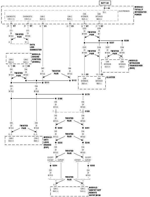
In the Wrangler for example, engine and drivetrain management operate on a 500 kB/s bus (CAN-C) and the interior functions like the radio and lighting operate on a separate 125 kB/s bus (CAN-IH). In addition, the Wrangler provides yet another 500 kB/s bus to the Data Link Connector for ODB reader use. (Diagnostic CAN).
ODB is only spoken on the Diagnostic CAN and the TIPM acts as a gateway. The internal networks are generally very busy with periodic broadcasts from the various modules.
The busses are bridged together by the Totally Integrated Power Module or TIPM. The TIPM also acts as a fuse box as well as a relay box to control the lights, horn, wipers. The TIPM use the CAN to communicate to the Engine Control Module (ECM), Electronic Stability Program (ESP) aka brakes, the anti theft systems as well as the Instrument Cluster.
Incidentally the TIPM is notorious for failing, so much so that there even was a class action lawsuit against Chrysler and even a company that specializes in repairing the TIPM.
And things go haywire if you disrupt the communications. The video below shows an example of what happens if you break communication to the Instrument Cluster.
The busses work together.
Let’s walk through an example how these devices and interact. You decide to turn on your headlights. The multifunction switch is part of the Steering Control Module (SCM) which monitors the position of that switch. The SCM is connected to the Instrument Cluster across a LIN connection. The Cluster polls the SCM periodically and notices that the position has changes and broadcasts the following CAN message.
2E1 [1] 0AThe CAN frame ID of 0x2E1 indicates headlight switch, it is one byte long and has a payload of 0x0A, which happens to mean headlight. The TIPM receives and decodes this message activates the proper transistors to turn on the headlights. The TIPM also has the ability to monitor the headlight current and protect this circuit as well as broadcast when the light fails.
The TIPM expects the headlight frame will appear periodically and if it doesn’t the TIPM will assume something is broken and will make available a trouble code for an ODB scanner.
Stay Tuned.
In the next article I will describe how you can attach your Raspberry Pi to the CAN and start reading data off the bus as well as maybe injecting a few commands.
If you want to get a bit deeper, I highly recommend you pick ups a copy of The Car Hacker’s Handbook by Craig Smith and for a real deep dive A Comprehensible Guide to Controller Area Network by Wilfried Voss.


I like these videos too. https://youtu.be/cAAzXM5vsi0 https://youtu.be/ZhYc95b6WoU https://youtu.be/ifjCRsCPfa4
also here - https://illmatics.com/carhacking.html