PiCar - Raspberry Pi Car Radio Project - Part 2
The Hardware
In the last installment I described list of goals for this projects. Now I would like to go over some of the hardware required to put this together. I have already written about some of the components and I encourage you to click on the links to see more details. I plan to dive a bit deeper in later installments about talk about some of the design decisions and lessons learned. For now, I present you an overview.
The Raspberry Pi
I started this project, before all the “experts” started screwing around with the supply chain and economy. Back then you could pick up a loaded Raspberry Pi 4 model B for somewhere around $50 - $75. Not so much so these days. You might have to settle for a Pi3 or 1GB Pi4 or possibly some of the alternatives. I hear that the Raspberry Pi Foundation is working on getting more out the door. You might have some luck with the rpiLocator tool.
The ARM Cortex-A72 in the Pi4 B turns out to be serious overkill for what I need to do right now. I chose this to prototype with and then maybe dial it down later , once I nail down what the actual performance criteria. Who knows though, I still have some plans for a few more features. So currently it’s a Pi4B.
The Pi 4B has fairly good USB and the 40 pin GPIO header, provides I2C and SPI as well as a few UARTs and 1 Wire interfaces. This invites lots of expansion opportunities, and there are number of add on cards and overlays available. Most importantly, the Pi can also be configured in a headless environment and a lot of the unnecessary fat cut away.
All in all, the Raspberry Pi is pretty robust and you can harden it with proper design. I have heard of it in a number of industrial and military applications. I guess that includes my chicken coop project.
I am currently using the 32 bit Raspberry Pi OS Lite, known as “Bullseye Debian”. Debian is based on linux and it has modern LLVM compilers and lots of drivers for things like CAN and I2C available.
I wrote most of my code using Clang C++ 11.
Don’t drain my battery
As shipped by the factory, the Pi is not exactly a perfect platform for a car radio project . Among other things the Pi lacks a low power sleep mode, the best you can do is get it into a shutdown state. Which means you really need to remove power from the Pi and it’s peripherals when you shut the car down. Otherwise you will quickly drain your battery (ask me how I know). Of course shutting down the Pi results in you rebooting the system when you turn the car back on, and suffering the time it takes.
Did I mention you need to remove power from the peripherals too.
The good news is that you can configure the Pi using the gpio-poweroff overlay to invoke a GPIO pin to indicate when it is safe to remove power.
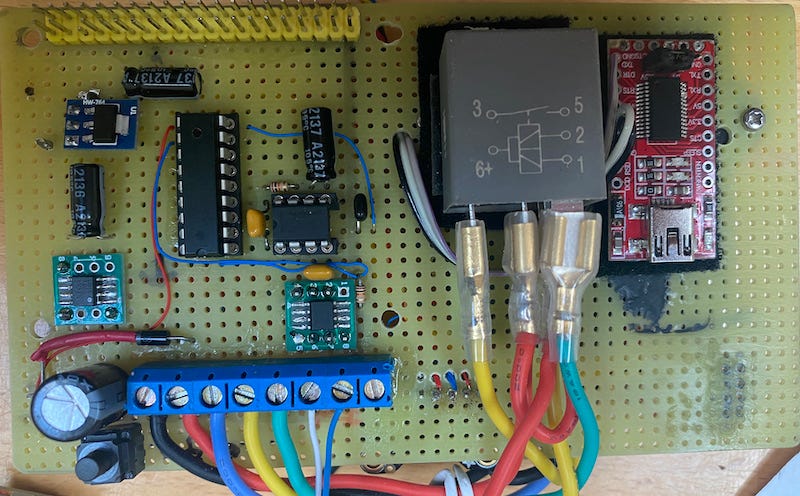
Given this constraint, I designed a power management board that will disconnect power from the Pi and it’s peripherals once it enters a shutdown state.
As for turning it on, the board has hardware that monitors the CAN bus and will restore power to the PiCar when the car starts producing CAN bus traffic again. For example. when you unlock or open the car door.
Turn it upside down.
While it’s cool that the Pi has so many add-on boards available that you can stack on the GPIO header, I found it shortsighted that, as shipped, the Pi is designed to be stacked upwards only. Specifically, the Pi 4 ships from the factory with pins soldered into the GIO pads rather than a stacking header.
While this works with many of the hobby projects that people build, it means that if you stack a board on top of the Pi, like a CAN interface, you will obstruct any thermal airflow directly above Pi heatsinks. This make the use of a fan board quite limited.
.This wasn’t acceptable for something that will sit just under the automotive dashboard, especially if you live in place that can often exceed 100°F in the summer. For this to work, the PiCar will need a fan above the CPUto keep the Pi within optimal operating temperature range.
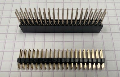
My solution was to carefully (and painfully) desolder the Pi’s GPIO header and replace it with a stacking header. Incidentally if you decide to do this, I recommend that you just cut the pins and plastic spacer off altogether and use a quality desoldering pump device. Oh and since the Ground pins are connected to a layer of its own, you will need to apply higher heat on certain pins.
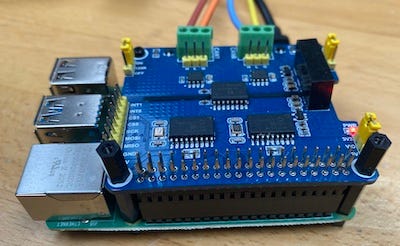
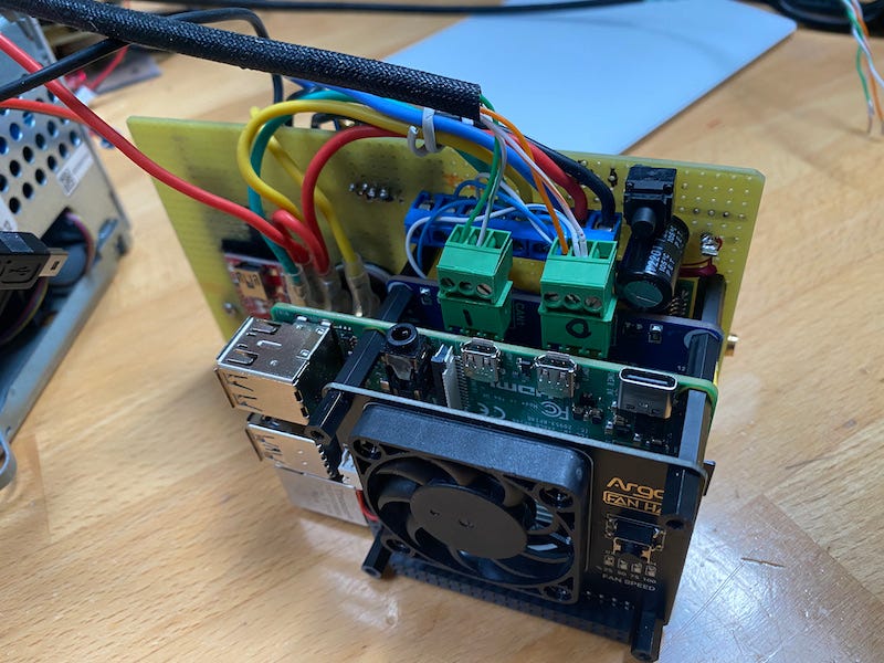
Once I finally got the header removed and the board cleaned up, I soldered in a stacking header and was able to stack a CAN interface card and my power management board below the Pi, and a fan on top.
Only Fans.
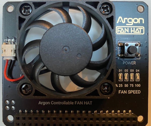
I did spend some time looking for a properly designed fan for the Pi. I wanted one that had could have it’s speed controlled by software and could move enough air to keep the CPU cool. After trial and error I discovered that the Argon fan hat was a perfect fit. It uses a 40mm cooling fan that can be speed controlled to CPU temperature. The controller board communicates over the I2C bus at address 0x1A and even has a button wired to toggle a GPIO4 pin for manual shutdown.
Argon does provide a python script available to control the fan. It’s a bit limited, but luckily DarkElvenAngel has been gracious enough to create an amazing piece of code, the Argon One Daemon. Written in C, the code runs on a variety of linux based OSs and includes a command line interface (CLI) and a documented API to control the fan speed.
An although it does works perfect as shipped, I made a few minor modifications to the code. In my PiCar project I happen to use GPIO4 for a serial port, and thus I removed the shutdown button feature.
The front panel
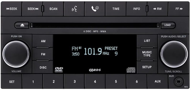
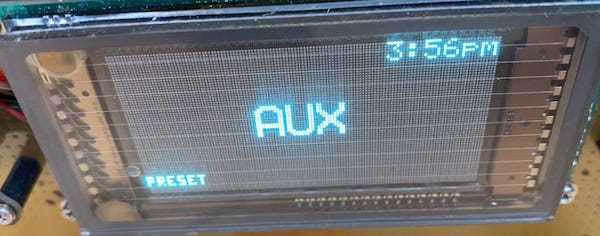
As I mentioned in the introduction article, I was striving for a slightly retro look and wanted to avoid the all so common OLED displays that I see in modern cars. The P05091164AB stock radio on the Jeep JK, used a VFD display, and I wanted to try to match that genre. Minus the myriad collections of buttons, easily replaced by a menu system.
The stock radio also shipped with a CD player, that truthfully I never used. The radio was designed before the popularity of iPod/iPhones. I was happy to delete it from my design. This functionality can be replaced by AirPlay or bluetooth using RPiPlay and a a2dp-agent. Or at the least an AUX input jack.
And really… if I wanted removable music media player that I would never use, I’d hunt down an old 8-track or cassette player.
VFD display
In the quest to create a similar look, I wanted a VFD display. I really liked the Noritake GU128x64D-K610A8 VFD Module. The VFD runs on 5 volts, and supports I2C, SPI and a CMOS compatible async serial interface.
The Noritake display is very bright and has good rugged environmental specs. The display controller firmware has 5x5, 5x7, 10x14 and 7x15 fonts and can also be pixel addressed.
I spent much trial and error with the I2C implementation, but later settled on async serial. While I could have connected directly to the Pi’s GPIO serial, I was running short of GPIO pins, taken by the other peripherals. So I opted for a USB interface, made possible by use of a FTDI USB to serial adapter. Adding a kittle more than $15 to the project.
By the way. I think I got the last one, as they also seems to be suffering from supply chain failures. There are a few other models floating around with similar spec, but I like this one.
The Control Knobs
We need controls for the volume and channel selection. This is a great time to mention how much I abhor car radios that don’t have a simple click on/off volume knob. Classic car radios have two knobs: The left knob is the volume control, and the right one the tuner. This is the proper way to do it – end of story. No matter what car you get into, you already know how to use the radio.
It should also have a backlight so you don’t have to fumble while driving at night.
So what I wanted for the knobs was an illuminated rotary encoder switch. There are a few of them out there, but I really liked the DuPPA I2CEncoder. The DuPPA store also had some nice aluminum knobs that can be backlit.
Who is DuPPA you might ask? They are two electrical engineers from Turin, Italy. who have some experience in the automotive tech field. On the side they make some pretty cool products.
But that wow factor, I decided to add LED rings around the encoder to provide dynamic feedback for the both the volume control and the tuner knobs. For this I used the DuPPa circular RGB LED rings. I was so impressed by these that I even wrote an article about it.
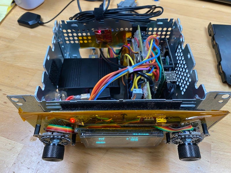
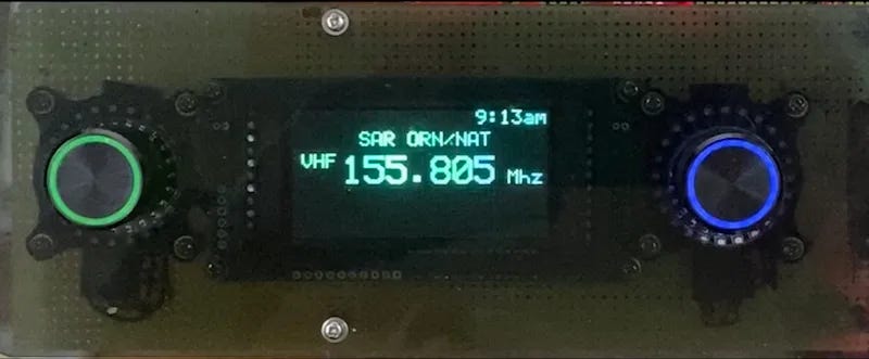
I prototyped the VFD, encoder knobs and LED rings on a Vectorbord, and cut a piece of smoked plexiglass as fascia plate. I will most likely 3D-print a proper face plate before final install.
The CAN bus interface
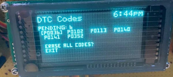
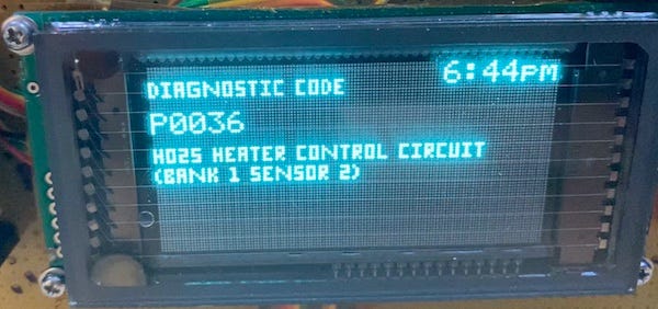
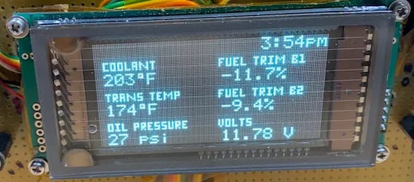
One of my project goals is supplant the “Check Engine” idiot light with something that can give me some details as well as optionally monitoring some of the vehicle’s subsystems. This will require me to tap into the Jeep’s CAN bus as well as the GMLAN that runs on the updated motor. This will require a CAN interface card.
I used the 2-CH CAN HAT from Waveshare. Walking through at the schematic, I particularly liked the Waveshare card because it uses an isolator and a Transient Voltage Suppressor to protect the Pi and it’s electronics from any potential voltage spikes from the automotive circuitry.
The card use a variation of the popular MCP2515 (CAN) controller interfaced over the SPI bus, and can benefit from the built in Raspberry pi driver. The nice thing about the driver is you can talk to the CAN network using the SocketCAN driver, and thus code using the standard unix socket API. Not to mention the can-utils , which are indispensable for debugging.
I wrote extensively a few months back about how to set this up. See my article about Hacking your Car Network.
GPS receiver
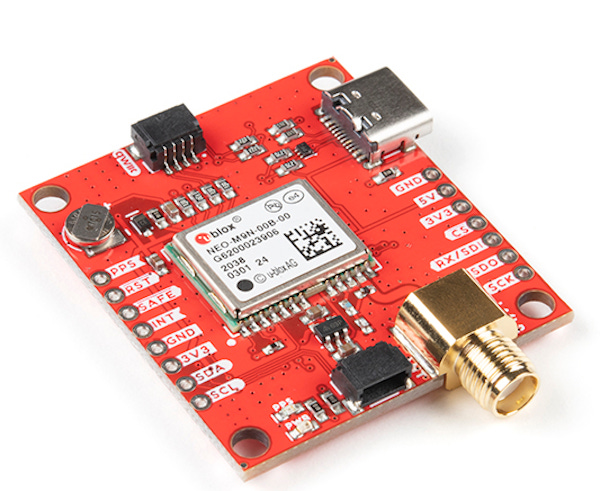
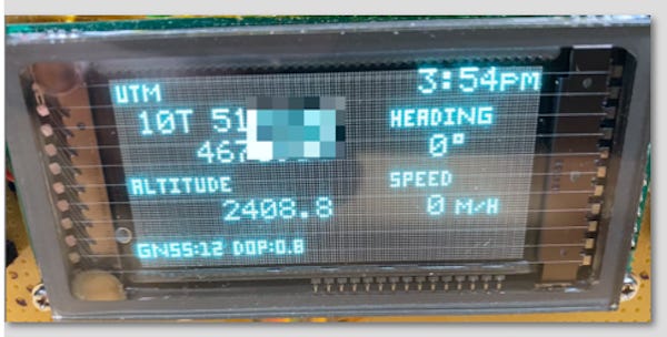
I happen to use GPS data for a number of things, particular when I don my “Search and Rescue” hat. There are a number of great GPS receivers on the market, but for this project I selected the SparkFun GPS Breakout which is based on the u-blox NEO-M9N-00B Standard precision GNSS module.
There is a lot to say about this device, I will detail that in a later article. I did a lot of experimentation with various interface modalities. I tried hard to make this an I2C device, but finally settled on using the built-in UART interface and powering it with 5 volts directly. Almost immediately the device started to send me NMEA GGA, GLL, GSA, GSV, RMC, VTG, TXT packets at 38400 baud.
I used a small GPS antenna in the prototype, but the jury is out on where it will be mounted for best reception in the final version.
It was a snap to decode these packets and produce useful information. I can also use the GPS data to keep the car radio clock set properly.
I plan to add some capability later to calculate distance to target as well as some additional programming of the device.
Software Radio
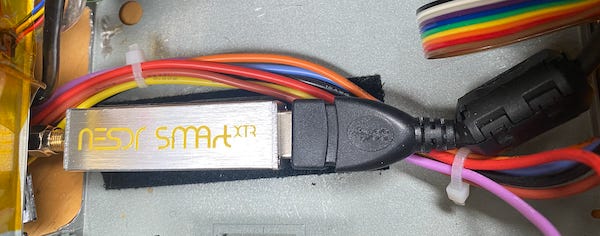
The primary goal of a car radio is to listen to radio broadcasts. Rather than to use a specialized tuner, I chose to go with Software Defined Radio using a Nooelec NESDR SMArTee XTR. This is basically a RTL-SDR compatible USB dongle with some fairly impressive specification for a relatively inexpensive (less than $50) device.
Using librtlsdr I was able to wrote code in C/C++ to talk to the device. The RTL-SDR samples the radio signals and provides a stream of quadrature I/Q values. This requires you to write a demodulator to process those values into Pulse Code Modulation (PCM) stream that the Raspberry Pi can convert electrical impulses to drive a speaker.
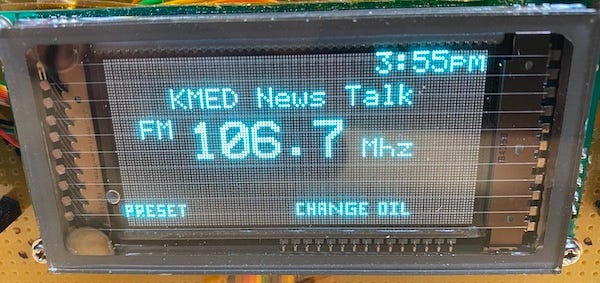
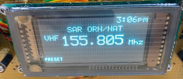
The SDR processing depends on the mode of encoding, such as broadcast AM, FM or VHF (NFM). Not everything converts to sound, some of the radio signals received can used to present data such as the TPMS tire pressure systems.
The magic behind the PiCar project is that it does manage to decode these signals with actually very low overhead. We can even go a bit deeper and add annotation to the channel display, using database to presents the driver and easy to understand and familiar form, regardless of the encoding modality.
Audio Playback
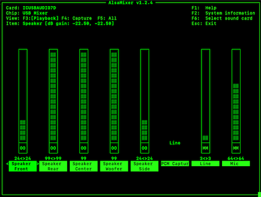
Once the SDR signal is processed into Pulse Code Modulation (PCM) form It can be passed to the native Advanced Linux Sound Architecture (ALSA) library present in the Raspberry Pi.
Since ALSA is that it provides a reasonably consistent API to audio input and output devices, it is easy to add your own sound cards to improve on the simple earphone jack on the Pi board. You can simply pick up a sound card online and plug it into the Pi with some minor hacking get it working in minutes.
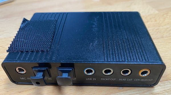
Since this is a car radio, I needed a way to handle both front and rear speakers. I did some experimentation and selected the VAlinks 6 Channel 5.1 sound card adapter.
The adapter communicates over the USB interface and provides stereo audio jacks for front and rear that I can feed into an audio amplifier. (possibly the stock Jeep one).
The sound card also provides me a LINE IN connection that I have successfully hooked up to my iPhone.
I wrote a function in the PiCar system that will take the encoded audio from the LINE IN jack and pump it back to ALSA all while maintaining the volume control control from the knobs.
A few more bell and whistles
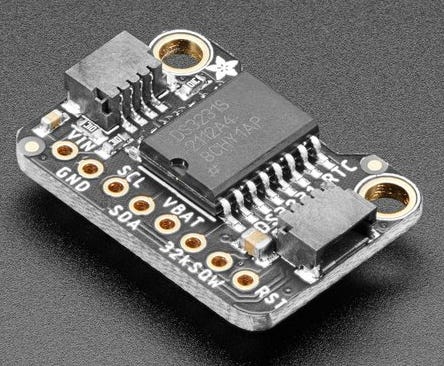
At least two more items are worth mentioning. Since the Raspberry Pi 4B doesn’t come with a built in Real Time Clock, you would have to suffer a way of setting it after each boot. Typically this is done when you have a network using NTP. But since this is a automotive application we need to maintain time between boots, and possibly when there is no GPS access.
I do this with a DS3231 real-time clock (RTC) module. In particular the Adafruit breakout board version, since it has a socket for a backup battery built into the board.
The DS3231 is extremely accurate and is temperature-compensated so it works well in an automotive application. Plus there is built in support in the the Raspberry Pi OS.
I’d like to also display the outside temperature. I added a 1-wire hookup from the Raspberry Pi to a DS18B20 Digital Thermometer that I will route to a safe location outside the vehicle.
The Enclosure.
All of this needs to somehow fit where the existing car radio is located. I was concerned that trying to match the proper double-DIN dimensions would require a substantial amount of work. Rather than to fiddle and fuss with that I opted to pick up a used Jeep/Dodge radio on eBay for cheap and gut it except for the enclosure itself. This guaranteed me a perfect fit.
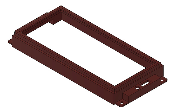
I asked one of the local 3D printing experts to scan and dimension the radio faceplate deleting all the features. I then plan to print a new one professionally with the proper cutouts for the knobs and smoked plexiglass for the VFD and rings.
This should make the physical installation match the current panel without much extra work.
More to come.
I wrote a lot more than I expected, but I want to overview the various hardware components that go into this project. There is a lot here. In later installments I will get into deeper details about some of the more challenging components, as well as an over view of how the software works. I will also post all the code open source as I usually do.
Thanks for sticking around. Till next time, my friends.


the code is on github -- https://www.vinthewrench.com/p/car-radio-build-notes.
there was no PCB -- made it by hand.
Great project! How possible would it be to get the codes, gerbers, and cad files? 😃