
Raspberry Pi Internet of Things - part 3
Reading from the 1-Wire sensors.

In a previous article, I wrote about controlling water flow to the crops. In this episode, I will talk about what I use to gather environmental data, such as temperature, humidity, rain detection, and how much water we have in our storage tank.
My code uses three methods to communicate with sensors: The Dallas 1-Wire® protocol, I²C, and GPIO. In this article, I will do a deep dive into the 1-Wire protocol and how I use it.
The Dallas Semiconductor Story
Dallas Semiconductor epitomized the spirit of the American startup. Founded in 1984 by a visionary team from Texas Instruments and Mostek. While U.S. giants like Intel and AMD engaged in fierce battles with Japanese competitors over the DRAM and microprocessor market, Dallas Semiconductor carved out a niche market by focusing on creating high-margin, specialized products that could be used in low-power industrial automation applications like vending machines or the early portable devices of the time. I encourage entrepreneurs to follow this link and read their story.
“Our goal is to make unique products cheaply.”
For example, they created a Real Time Clock chip that included a built-in crystal oscillator and battery management, or pairing the lithium batteries used in wristwatches of the time with CMOS memory chips.
Dallas also developed the Crypto iButton, aiming to establish it as the standard method for verifying the identity of Internet users. Some early pioneers even suggested its potential as a cryptocurrency storage device.

Dallas Semiconductor went public on the NYSE just three years after its founding. In 2001, Maxim Integrated Products purchased it for $2.5 billion. In 2021, Maxim itself was acquired by Analog Devices.
The 1-Wire® Protocol
The existing device protocols of the time, like I²C and SPI, required multiple connections for data, clock, and power. The folks at Dallas saw an opportunity to lower manufacturing costs by reducing the number of physical connections to the device and simplifying the application design. The 1-Wire protocol did this in a number of ways.
Single-Wire Communication - They used a single data line (along with ground) for bidirectional, half-duplex communication by employing an open-drain bus with a pull-up resistor. This allows master and slave devices to pull the line low to signal data.
Parasitic Power - Dallas capitalized on their expertise with low-power CMOS and battery-backed memory and created a system where the slave devices can use the same line that communicates data to charge an internal capacitor, thus supplying power to the device. This removes the necessity for a dedicated power line.
Unique Device Addressing - Every 1-Wire slave device is assigned a factory-programmed 64-bit ROM address. This eliminates the need to configure jumper wires and avoids the address collision issues that can be a problem in I²C and SPI. (Try to use two SHT-30 humidity and temperature sensors on the same I²C bus.) A clever binary tree search algorithm is also used to find devices on the bus. This makes it possible to create a large sensor array using this protocol.
Minimalist protocol design. - The command set is simple enough to be implemented on a low-cost device like a PIC microcontroller, or in our case, bit-banged on a Raspberry Pi GPIO line.
1-Wire Sensors
One of the most common 1-Wire devices is the DS18B20 temperature sensor. These devices are commonly available in pre-wired waterproof packaging with a 1-meter cable in 5 packs for about $1.20 to $3 per sensor.
According to their datasheet, they can measure temperatures from -55°C to +125°C (-67°F to +257°F) with ±0.5°C accuracy. And consume less than 1.5mA while taking measurements.

1-Wire using Raspberry Pi GPIO
There are two ways to connect a Raspberry Pi to the 1-Wire® Protocol. You can implement it entirely with software by bit-banging the protocol, or use a DS2482-100 to bridge it from I²C.
Bit-banging refers to the use of software to create a serial protocol. The Linux used in the Raspberry Pi has a kernel overlay that dramatically simplifies the connection of 1-Wire devices to the GPIO lines.
Let’s look at the first alternative, which is using the GPIO pin.
Examining the documentation at /boot/overlays/README, we find:
Name:   w1-gpio
Info:   Configures the w1-gpio Onewire interface module.
        Use this overlay if you *don't* need a GPIO to drive an external pullup.
Load:   dtoverlay=w1-gpio,<param>=<val>
Params: gpiopin                 GPIO for I/O (default "4")
        pullup                  Now enabled by default (ignored)


Name:   w1-gpio-pi5
Info:   See w1-gpio (this is the Pi 5 version)


Name:   w1-gpio-pullup
Info:   Configures the w1-gpio Onewire interface module.
        Use this overlay if you *do* need a GPIO to drive an external pullup.
Load:   dtoverlay=w1-gpio-pullup,<param>=<val>
Params: gpiopin                 GPIO for I/O (default "4")
        extpullup               GPIO for external pullup (default "5")
        pullup                  Now enabled by default (ignored)


Name:   w1-gpio-pullup-pi5
Info:   See w1-gpio-pullup (this is the Pi 5 version)
So all we need to do is add this to the /boot/firmware/config.txt file; the operating system does the rest.
# hook up one-wire for temp sensors on line 4
dtoverlay=w1-gpio,gpiopin=4
Theoretically, a 4.7k pull-up ( 3.3V / 4700 ≈ 0.7mA ) resistor on the GPIO line would provide enough parasitic power to the 1-Wire device.

However, as I mentioned in my Raspberry Pi Car Radio Project article, many counterfeit 1-wire devices—especially the DS18B20 temperature sensors available on the market—cloned by those industrious folks in the PRC, do not perform well in parasitic power mode, or at all. In this case, you must also supply power to the devices.

1-Wire using a DS2482-100
Another problem we might encounter on a farm is that a 1-wire device may be placed relatively far from the Raspberry Pi, for example, a few hundred feet. In this situation, the internal capacitance of the cable will be so high that the 4.7k resistor is insufficient to charge the cable capacitance quickly enough to reach a logic high level with the 1-Wire timing specifications.
The DS2482-100 is an I²C to 1-Wire bridge that addresses this issue and can also offload some of the processor’s workload related to generating time-critical 1-Wire waveforms.

There is even a user-space driver called the One-Wire File System, not to be confused with the one-wire kernel overlay I described above. While both provide access to the 1-Wire devices over the file system, this runs as a user process and requires a little more setup.
Both systems communicate with the 1-wire device and make the data available as data in a file.
For example, let’s assume we have a DS18B20 sensor with the serial number 283c89f6494824. Since the family number of these devices is 0x28, it will always be the first byte of the serial number and the directory containing a file named “temperature”.
Using the w1-gpio kernel overlay, the file path to the temperature file will be:
$cat /sys/bus/w1/devices/28-3c89f6494824/temperature
34625
Divide this value by 1000 to get 34.625°C.
However, the file path to the temperature data would differ if we use the DS2482 and the One-Wire File System.
$cat /mnt/1wire/28.3c89f6494824/temperature
34.625
Note that the value might have a decimal, and it might not. I have seen both. Also, I'd like to point out that the directory representing the device serial number is slightly different.
We apply the conversion formula F = (C × 9/5) + 32 in both cases and get 94.325°F.
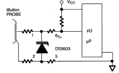
I found a Raspberry Pi add-on board called the 1-Wire Pi Plus from AB Electronics in the UK that not only uses the DS2482-100 chip but also adds a DS9503 for electrostatic discharge (ESD) protection. The schematic shows a well-thought-out design.
Electrostatic discharge (ESD) protection
During my research, I came across a Raspberry Pi add-on board called the 1-Wire Pi Plus from AB Electronics in the UK that uses the DS2482-100 chip but also adds a DS9503 for electrostatic discharge (ESD) protection. Their schematic shows a well-thought-out design, and the quality of the product and the documentation were excellent.
The DS9503 chip is recommended for ESD protection of 1–Wire interfaces. There is some excellent information on how this works in the DS9503 datasheet.
While I am currently prototyping with DS2482 and the 1-Wire Pi Plus board, I am still considering using the w1-gpio kernel overlay and incorporating the DS9503 into the design. The GPIO pins on a Raspberry Pi operate at 3.3V, have limited built-in ESD protection, and are sensitive to overvoltage. Whether I run the sensors in parasitic power or not, I will incorporate an Isolated DC-DC 5V power supply to prevent ESD from leaking back to the Raspberry Pi Power. The Polulu 5384 should provide about 2.5 kV of isolation and appears to be a perfect fit.
On the other hand, if I stay with the DS2482, I will most likely write my own I²C driver and focus on reliability by tracking the number of errors, data, and ground shorts.
If you want to learn more, consider reading the Guideline for Reliable Long 1-Wire Networks.
Let’s bury this topic.
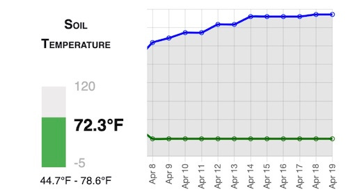
I like the DS18B20 sensors, and they are perfect for my agricultural use. I even buried one of these sensors a few inches into the ground to determine when the soil was ready for various crop starts. I even wrote code into the piotserver to track high and low temperatures for each 24-hour segment.
In my next article, I will discuss the various I²C devices I chose and how I connected them to my system.
Another fun read, Vin... note that the temp conversion equation should be F = (C × 9/5) + 32