Rings and Knobs
So cool, you might need to find a use for it!
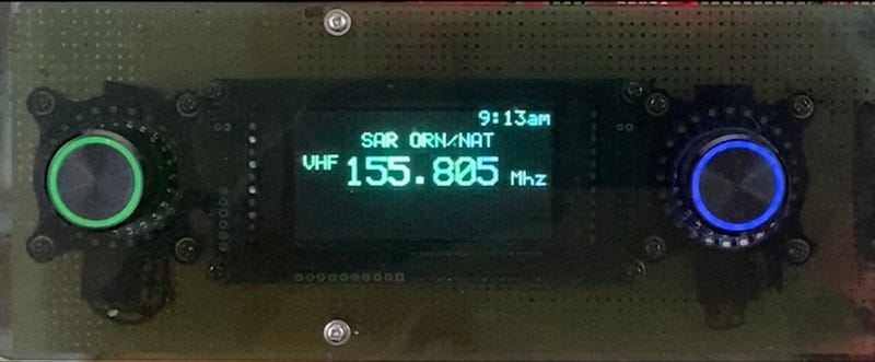
Sometimes you find something so cool you need to find a use for it. But this is not that case, well sort of… I am in the process of creating a RTLSDR car radio and wanted to find a pair of rotary encoders for the tuning and volume control knobs. Ideally one that I could backlight for night driving.
I did manage to find a couple of products with I2C interfaces to process the encoding. But nothing that felt smooth and professional enough for what I am creating.
After some trial and error, I came across the perfect fit; The I2CEncoder from DuPPa. Never heard of DuPPA? DuPPA is two electrical engineers from Turin, Italy. Apparently from the automotive tech field, and they make some pretty cool products on the side. I will talk about two of devices I am using: the rotary encoder and the LED ring.
It’s all in the Encoder.
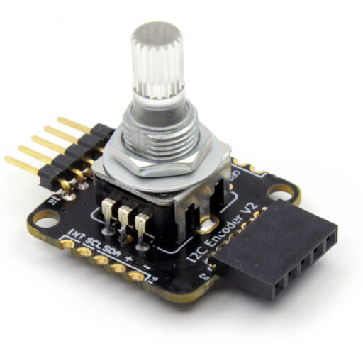
While DuPPA I2CEncoder can be ordered as a board, I chose to pick up the version that has an illuminated rotary encoder already soldered in. The DuPPa uses the the PIC16F18345, a chip that not surprisingly given the engineers background, is a star even in harsh automotive environments. The circuit takes input from the rotary encoder and presents itself as an I2C device, It can also drive a RGB LED for backlighting the encoder.
Bit that wasn’t enough for the DuPPA engineers, they also through in GPIO, PWM and analog connections on the board.
Oh and yes, the entire project is open source on GitHub including the hardware Gerber and AutoCad files! Wow!
All this for about $10 USD. And while you are at their store, DuPPa also something I was having a hard time finding elsewhere, a set of high quality aluminum knobs with a translucent rings for the backlight. These are available for about $2 USD, in both black and silver.
It’s a rotary encoder you say, so what’s the big deal? It’s the features built into the firmware. They really thought about what you would want in an illuminated encoder and even did the PWM and gamma correction for the LED. The GitHub page provides a Python library and quit a bit of Arduino code. The manual is incredible instructive and details the features pretty well.
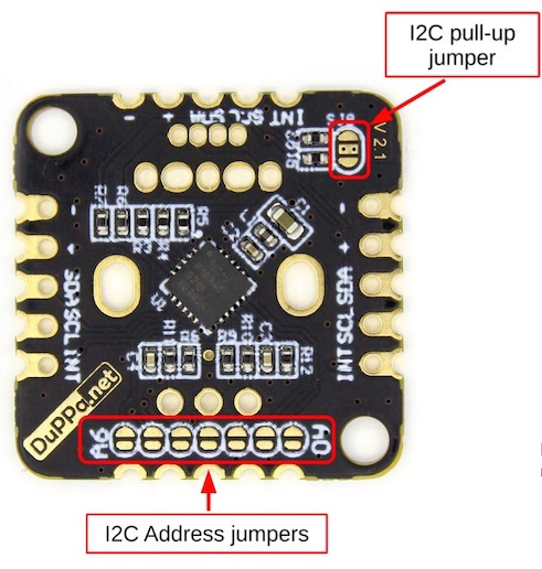
The encoder is fairly easy to setup, solder the appropriate jumpers in place as well s the I2C pull-up jumpers and hookup SCL/SDA +3v and GND to your Raspberry Pi I2C lines. The device can work on 3.3v as well as 5v. Which make OK for Arduinos. But I stuck with 3.3v since the Pi isn’t really tolerant of 5v signals.
There is also an open-drain interrupt (INT) signal available that can be wired to pull a Raspberry Pi GPIO signal low when an event such as rotating or clicking the encoder occurs. Actually the interrupt can be configured a variety of ways; including things like double click and limit detection. There is even a feature related to programming the fading LED.
Programming this Puppy
In spite of its collections of features programming the device is quite simple. While there are a number of I2C registers available on the encoder, you only need to know about a few to get basic functionality.
You use the GCONF general configuration register you setup with things like direction of rotation and INT signal resistor pull-up. And if you chose to use the INT, you can setup the INTCONF register to specify what actions you want interrupts for.
Or you could chose to ignore the interrupt feature altogether and simply poll the device looking for changes. In my case I have a lot of things going on in my project, and went with the interrupt feature to minimize CPU time.
After digging into the I2CEncoder manual I was able to write up my own C++ interface class and sample code, which I made available open source. In my sample I took two encoders and wired them up to I2C address 0x40 and 0x41. I also attached the INT line to GPIO27 (pin 13 on the Raspberry PI GPIO header). You can build it with or without the INT.
I have a C++ DuppaEncoder class that is built upon the I2C class I use in many of my projects.
The code to setup the encoder knob looks like:
DuppaEncoder knob1;
int  errnum = 0;

uint8_t config = DuppaEncoder::INT_DATA
		| DuppaEncoder::WRAP_DISABLE
		| DuppaEncoder::DIRE_LEFT
		| DuppaEncoder::IPUP_ENABLE
		| DuppaEncoder::RMOD_X1
		| DuppaEncoder::RGB_ENCODER;

uint8_t interrupt_config =
			DuppaEncoder::PUSHR
		| 	DuppaEncoder::PUSHP
		| 	DuppaEncoder::RINC
		| 	DuppaEncoder::RDEC ;


// Open device

if(!knob1.begin(0x41, config,interrupt_config, errnum))
   throw Exception("failed to setup knob1 ", errnum);

// turn on the green backlight
if(!knob1.setColor(0, 0, 255))
    throw Exception("failed to setColor knob1 ");
Polling the device
To check for activity, your code should read the ESTATUS register. NOTE: the read will clear the register, so your code needs to record it if your polling and processing code are separate.
As an example ,here is how you could code a polling loop to track click and movement. I use one loop to check for changes and an outside one to process them. After I handle a click or move, I check again for changes before sleeping.
uint8_t status = 0;

while(){

// loop until status changes
 for(;;) {

// get status from knobs
      knob1.updateStatus(status)

// if any status bit are set, process them
      if(status != 0) break;

//else sleep a while check back later.
     usleep(2000);
    }

// process the status
   if(status != 0){
       bool cw = false;

   if(knob.wasClicked())
	printf("Knob Clicked \n");
   }

   if(knob.wasMoved(cw)){
	printf("Knob moved %s\n", cw? "CW": "CCW");
   }
}
Using GPIO Interrupts
Rather than periodically sleeping the thread, you could use GPIO interrupts to wake when something changes. It is slightly more complicated, but not that hard.
Rather than having to write a kernel module, it is possible to access the Raspberry Pi GPIO system in user space through the character interface and various ioctl calls. A better choice is to use the gpiod library which does a fair job of abstracting the ABI (Application Binary Interface) .
While I believe Raspberry Pi comes with libgpiod preloaded, you will need to do to install the gpiod developer interfaces.
sudo apt-get install gpiod libgpiod-devThis will also provide you some good debugging tools for working with the GPIO lines. The sources and docs to gpiod are also open source on GitHub.
At the code level, you will link in the gpiod library and include the <gpiod.h> header with your compile..
Some Raspberry Pi boards abstract a number of gpio systems, If you want to experiment try the gpiodetect and gpioinfo shell command. As far as I can tell we always use /dev/gpiochip0 to get the Broadcom device.
Expanding on the above example for the DuPPA encoder, your code will also need to setup the GPIO lines for detecting the interrupt.
Open the
gpiointerface withgpiod_chip_open.Get a ref to the line you wish to work with using
gpiod_chip_get_line.Setup the GPIO Line to detect falling edge events (the INT line going low) using the
gpiod_line_request_falling_edge_events_flagscall.
#include <gpiod.h>

#define GPIOD_TEST_CONSUMER "gpiod-test" // whatever you want

struct gpiod_chip*  _chip = NULL;
struct gpiod_line*  _line = NULL;

// setup GPIO27 as connected to the duppa INT line

const char* gpioPath = "/dev/gpiochip0";
constexpr uint gpioLine	= 27;

// open the GPIO driver
_chip = gpiod_chip_open(gpioPath);
if(!_chip)
  throw Exception("failed  gpiod_chip_open ");

// get a refs to the GPIO Line
_line =  gpiod_chip_get_line(_chip, gpioLine);
if(!_line){
  throw Exception("failed gpiod_chip_get_line ");

// setup the line for input and select pull up resistor
err =  gpiod_line_request_falling_edge_events_flags(
                 _line,
	          GPIOD_TEST_CONSUMER,
                  PIOD_LINE_REQUEST_FLAG_BIAS_PULL_UP);
if ( err )
  throw Exception("failed request_falling_edge ");
At this point the GPIO line 27 is configured for input and has a pull-up resistor programmed in.
Using interrupts, our loop example is slightly different that the one above. As before, we loop checking for status changes, but when we find no change, instead of just sleeping for a period of time using usleep, we cause our thread to suspend using the gpiod_line_event_wait call.
We can still optionally pass a timeout period to the gpiod_line_event_wait, or just pass NULL to sleep until woken by the interrupt. The event wait ABI will return after an event occurs, in our case the GPIO line going low, with a return value of 1. If we chose to specify a timeout, and enough time goes by, it will return with a 0.
At that point your code should call gpiod_line_event_read to reset the event, else we will return immediately from the next time we call the event wait ABI.
At this point we loop back to the top of the for loop and query the know with another call to my DuppaEncoder::updateStatus()function.
Here is the modified status check loop.
uint8_t status = 0;

while(!quit){

// loop until status changes
 for(;;) {

// get status from knobs
      knob1.updateStatus(status)

// if any status bit are set process them
      if(status != 0) break;

      struct timespec timeout;
// Timeout of 60 seconds, pass in NULL to wait forever
	 timeout.tv_sec = 60;
	 timeout.tv_nsec = 0;
        gpiod_line_event evt;

 // gpiod_line_event_wait return 0 if wait timed out,
 // -1 if an error occurred,
 //  1 if an event occurred.

err = gpiod_line_event_wait(_line, &timeout);
 if(err == -1)
   throw Exception("failed event_wait");

// gpiod_line_event_wait only blocks until there's an
// event or a timeout, it does not read the event.
 // call gpiod_line_event_read  to consume the event.

   else if (err == 1) {
      gpiod_line_event_read(_line, &evt);
   }
    else if (err == 0){
	 printf("timeout\n");
   }

// process the status
   if(status != 0){
       bool cw = false;

   if(knob.wasClicked())
	printf("Knob Clicked \n");
   }

   if(knob.wasMoved(cw)){
	printf("Knob moved %s\n", cw? "CW": "CCW");
   }
}
One important note.. When we are done with our work, it is prudent to release the GPIO line with gpiod_line_release and gpiod_chip_close.
if(_line)
   gpiod_line_release (_line);

if(_chip)
  gpiod_chip_close(_chip);
Running the test code.
But Wait!
This sample demonstrates minimal viable functionality, but the there a lot more that I didn’t touch on. There is other cool stuff build into the encoder, including: The LED fader, rotation counter, debouncing, GPIO, PWM or Analog converter.
Oh and there is a 256 bytes of EEPROM you can fool with too.
Accessorize with a ring.
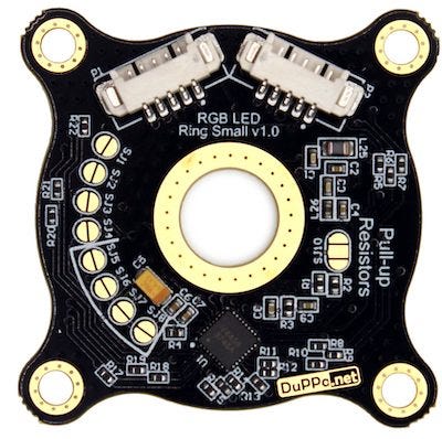
Truly, I would have been happy with just the I2CEncoder, but then I perused at the DuPPA site some more, and came across the LED ring. This was so cool, I had to find a use for it.
I’m trying Ringo.. I’m trying real hard.
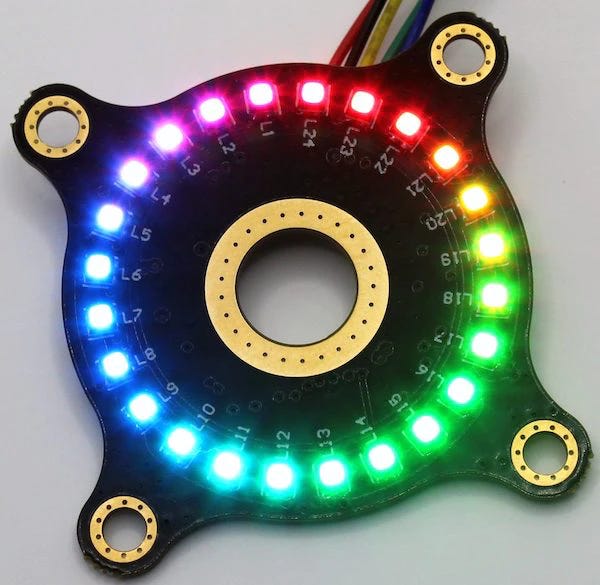
DuPPA created a circular LED board with a 9mm hole that slides over the rotary encoder shaft. Actually they have two models one with 24 RGB LED and a larger one with 48 LEDs. As with the encoder, the LED ring is also open source along with the Gerber and AutoCad files
I used the smaller LED ring which cost around $11 USD. It is based on the Lumissil Microsystems IS31FL3745 LED driver chip. As with the encoder, this is another I2C device. You can program its address and pull up resistors with solder jumpers on the backside of the ring.
There are a pair of 5 pin Molex 532610571 PicoBlade connecters on the back. A lot less fragile than the Qwiic connectors that I so often break. It has the usual SDA/SCL line with the addition of a LED supply voltage line. In my case I attached it to the +5v supply, rather than push the Raspberry Pi 3v regulator I use for I2C.
I had to dig through the IS31FL3745 datasheet a bit and the DuPPa schematic and the Arduino sample code to figure out what is going on. The RGB LEDs are wired into a 6x8 matrix, well actually since it’s RGB its 18x8 matrix, and the driver code needs to create a map for which LED is at what address.
The IS31FL3745 has two modes, one for current setup and one to control the PWM for each LED.
In my C++ sample code I created a DuppaLEDRing class that makes this easy to use. In this case I wired the LED to address 0x61.
DuppaLEDRing led;
int  errnum = 0;

// setup the LED
if(!led.begin(0x61, errnum))
    throw Exception("failed to setup LED   ", errnum);


// the LEDS are mechanically reversed from the CW movement
// of the knobs - so reverse them and offset one of them
    led.setOffset(2, true);

// run one cycle of LEDS  on and off
    for (int i = 0; i < 24; i++) {
       led.setColor(i, 0,255, 0);  // (rGb)
       usleep(20 * 1000);
     }

  for (int i = 0; i < 24; i++) {
       led.setColor(i, 0, 0);  // (rib)
       usleep(20 * 1000);
     }

// release the memory when done.
  led.stop();
What’s next.
The LED ring and encoder combo is giving me the ability to do some interesting things. For example, I was able to create dynamic feedback for the volume control knob on the radio project.
Since you have full control of each LED through the PWM I am sure you can come up with a number of great ideas.
Happy Hacking!


