
Chasing Raspberry Pi Power Management
Lessons Learned Building a Power Switch with Deep Sleep and Wake Control

The problem of Raspberry Pi power management has been dogging me for a few years now, going back to my Pi Car Radio project in 2022. That project forced me to confront the real issue early on. The Raspberry Pi does not do deep sleep. It was never one of the design goals. You can shut the operating system down, but the board stays powered and continues to draw current. That is not practical unless you like dead batteries.
There are products and add-on hats that try to address this, and some of them work fine within their limits, but they are partial solutions. Most of them assume the Pi is the system and that only the Pi needs to be managed. My problem was different. I needed power management as part of a larger system, in this case an irrigation controller with solenoids, valves, and real loads, where saving battery and enforcing power state matters more than keeping the Pi alive.
Why Shutdown Is Not Enough
Shutting down the operating system is only part of the problem. It solves file system integrity, not power management. After shutdown, the Raspberry Pi is still powered, still drawing current, and still connected to everything downstream. Even if the Pi is only drawing 25 mA in this state, which sounds small, it runs 24/7. That is just a slow battery leak, like a tire with a nail in it. It does not fail all at once, but soon enough it will leave you with a dead battery.
If the goal is to save energy, power has to be physically removed, cutting power to the Pi and to anything else it might be controlling. Once you do that, the Pi is dead and out of the loop. It cannot wake itself.
That means something else has to decide when power comes back. In my case, that happens for a few specific reasons. The system needs to wake when AC power is restored. If AC is not available for a while, it still needs to wake on its own to do periodic work, things like taking environmental measurements, updating state, or activating and deactivating devices such as irrigation valves and sprinklers.
Since those decisions cannot depend on the now unpowered Pi, the wake logic has to live somewhere else, in hardware that stays alive when everything downstream is off and can make those decisions without Linux running.
Why the Early Designs Fell Short
In earlier versions of this work, I tried to solve the wake problem with discrete components. Simple logic to detect power restoration, edge detection, delays, and restart conditions. It worked on paper and sometimes on the bench, but in practice it was finicky. Small variations in timing, component tolerances, and real-world power behavior made it unreliable. As the system got more complex, those approaches stopped scaling.
What I needed instead was a microcontroller. Modern MCUs can stay alive at very low power, make clear decisions, and handle timing without depending on RC delays, thresholds, and other analog behaviors. That also made it possible to add controlled, timed wake logic, not just react to power coming back, but wake on purpose to perform scheduled work when nothing else was happening.
What It Needed to Do
The nice thing about building enough iterations of this design is that I have a good handle on what this power controller needs to look like now.
Remove power from the Raspberry Pi and all downstream loads in response to a shutdown request from the Pi.
During shutdown, draw minimal power so the system can remain off for long periods on battery without slowly draining it.
Automatically bring the system back up when AC power is restored or on manual request.
Support scheduled wakeups to perform periodic work while running on battery.
Beyond that, it needed to fit cleanly into my existing irrigation controller design and be generic enough to reuse in other systems without redesigning the power logic each time.
MCU Design Evolution
Once it was clear that this problem needed a microcontroller, the question stopped being whether to use one and became which one to use and how the Pi interacts with it. I²C was already in use elsewhere in the irrigation controller, so reusing it for the power controller was a no-brainer.
Those choices narrowed the MCU requirements to an MCU that truly supports I²C slave operation, a small number of GPIO lines, and a low-power sleep mode with timed wakeup.
I looked at a few MCU families, including AVR, PIC, and ESP. All of them technically could have been made to work, but AVR ended up being the best fit for this design.
PIC parts are capable, but the toolchain alone was enough to raise concerns, and the added complexity of configuration bits and device-specific sleep and wake quirks did not offer enough upside to justify adding a new ecosystem to my designs.
ESP-class parts are designed for connectivity-first systems, not for quietly managing power while everything else is off. Their higher baseline power draw, more complex boot sequence, and built-in Wi-Fi, radios, and background behavior add power cost that is hard to justify for a controller whose primary job is to sleep most of the time.
AVR ended up being the best match for the job. The parts are simple and electrically well understood, with solid I²C slave support and low-power sleep modes. The toolchain also fit naturally with my existing workflow, using C and Makefiles, with no extra framework garbage.
Once AVR was the clear direction, the next step was narrowing down the specific part.
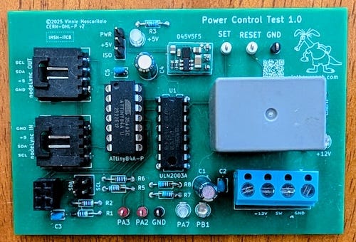
This took a few tries. I aimed low at first with the ATtiny84A-P. It had low-power sleep modes, enough GPIO to get started, and was easy to prototype. But the devil was in the details. I²C slave support was workable but fragile, pin count left no margin, and interrupt and wake handling became awkward as soon as more than one wake source was involved. Every small change forced compromises that were exactly what I was trying to avoid in a power controller.
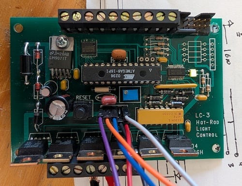
My next try was the ATmega8-16. I had used this part before in a model railroad semaphore controller and in a custom car lighting system, so it was already terra cognita. This got me further than the ATtiny84, but it ultimately hit a dead end around sleep and wake behavior.
While the chip could sleep and wake, combining low-power sleep with multiple wake sources, including timed wakeups, became awkward and brittle. Only a limited set of interrupts remain active in the deepest sleep modes, and timer availability is sharply reduced there. Getting all of my requirements to coexist meant giving up the deepest sleep modes and accepting unacceptably higher power usage.
On top of that, the ATmega8 is now flagged as NRND (Not Recommended for New Designs), which made it a poor foundation for something I intended to keep building on.
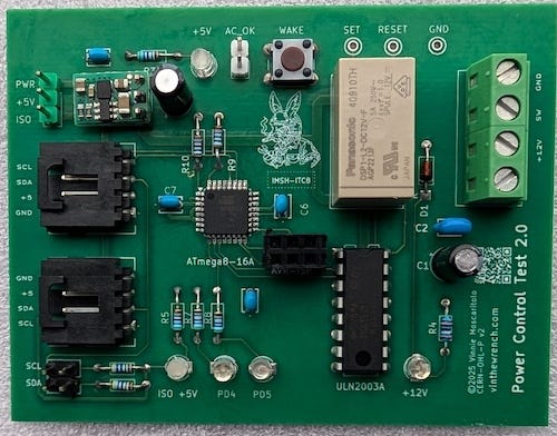
Fortunately, there was a closely related part that addressed the sleep and wake limitations without changing the overall design. That part was the ATmega88. It cleaned up the interaction between sleep modes, interrupts, and timers in a way the ATmega8 never quite managed. It made it possible to stay in the deepest sleep states while supporting multiple wake sources and timed wakeups, without resorting to special cases or power compromises. In practice, the behavior was more predictable across sleep transitions, which is exactly what you want in a controller that exists to manage power.
The swap to the ATmega88 was easy, using the same TQFP package, pinout, and development workflow, while avoiding the ATmega8’s NRND status at nearly half the cost. It was largely a matter of swapping parts, not redesigning the board.
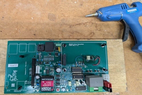
Standalone Prototype Board
As this design evolved, one decision that helped a lot was pulling the power controller out into a standalone breakout board. Instead of repeatedly reworking the irrigation controller, I isolated the power logic and treated it as its own subsystem. That made it much easier to debug wake behavior, power transitions, and failure cases without dragging the rest of the system along for the ride. It also forced the design to be self-contained, which made it easier to reason about and reuse elsewhere. Once the power logic worked on its own, integrating it back into the irrigation system was straightforward.
How I Learned to Stop Killing MCUs
Another lesson that came out of this design evolution had nothing to do with the MCU itself and everything to do with how the firmware gets onto the board. In earlier versions of this project, I managed to kill more than one chip by being careless with ISP programming. Programming over ISP is simple enough, but hot-plugging an ISP cable into a powered board can back-feed signals through protection diodes or I/O pins in ways the chip really does not appreciate. Sometimes you get away with it. Sometimes you do not. I did not, more than once.
That experience led to one more revision of the breakout board. I added small series resistors on the ISP lines. This is not a substitute for good habits, but it does help limit the damage when I inevitably screw up.
Firmware
Once the power controller moved to a microcontroller, I needed to create firmware to run the logic. The good news is that the code itself is fairly simple.
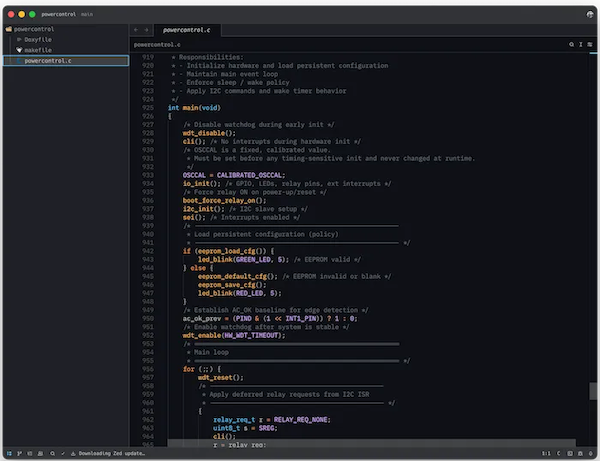
The controller runs as an I²C slave at a fixed address and exposes a small command set. The Raspberry Pi can request a power-off by opening the relay and can set a wake timer for a future restart. Once power is removed, the MCU enters a deep low-power sleep mode and waits for a wake event, such as AC power returning, a watchdog-based timer expiring, or a user wake button.
In its deepest sleep state, the controller draws about 350 µA. That is not the absolute minimum possible, but it is low enough for my application. With the 12 V 22 Ah SLA battery I am using, that level of current works out to years of standby time. At that point, battery self-discharge and real work cycles matter far more than the controller itself. Chasing lower numbers would have meant more hardware complexity for very little practical gain.
Because this started life as a standalone breakout board, I added a couple of LEDs that can be toggled from the Raspberry Pi over I²C to make bring-up and debugging easier. I also added a jumper to select how the MCU is powered, either from the Pi’s 5 V rail over I²C or from the onboard regulator tied to the 12 V system supply. That flexibility made it easier to test and isolate power behavior during development.
The firmware is written in straight C, built with avr-gcc, flashed with avrdude, and driven by a Makefile. I opted away from the Arduino IDE because getting the power savings I needed required full control over what the code does. I could not rely on third-party libraries or hidden startup behavior for something this critical.
The Build Process
If you want to see how this board really came together, I lay out the whole process in my article How Did You Make That? It walks from the first sketch through schematic capture, PCB layout, fabrication, flashing, and debugging. It’s the unglamorous middle part between an idea and hardware that actually works.
And if you want to dig a bit deeper into the details, I’ve put the entire project on GitHub. As I usually do, the source code, KiCad schematics, and PCB layouts are all open, under permissive licenses that let you use, modify, and build on the work and pretty much do whatever you want.
If you care about how things are made and why they’re built the way they are, you’ll probably like the rest of what I write about. Hitting like and sharing helps real people find the work. The algorithm can go pound sand.
Nice one