

Hacking your Car Network - Part 2.
Get on the bus, Gus.

In the last episode of Hacking your Car Network I talked about the Controller Area Network (CAN) and how it is used to move data cross the various control units and modules used in most modern vehicles. In this installment, I will talk about how you can hook up your own hardware to the CAN, and how to inspect that data on it.
The first thing we are going to need is some form of interface card. There are a few different ones available for the Raspberry Pi, or if you chose to, you could choose to roll your own. Most of the cards out there use a variation of the MCP2515 (CAN) controller, as this easily interfaces with the Raspberry Pi using SPI.
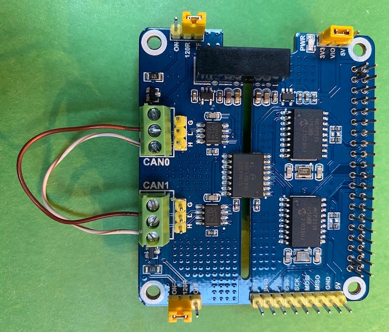
Two of my favorite CAN cards for are the 2-CH CAN HAT from Waveshare and the PiCAN2 Duo from SK Pang Electronics Ltd. I managed to pick up the Waveshare card for less than $30 from Amazon.
Looking at the schematic I particularly liked the Waveshare card because it uses an isolator and a Transient Voltage Suppressor to protect the Pi and it’s electronics from any potential voltage spikes from the automotive circuitry.
The Waveshare device comes with a 40 pin header extension and plug in easily to the Raspberry Pi and the Pi Zero.
Be careful to not prick your fingers with the headers, or so a friend told me 😬…
Once you install the card, Double check that the PWR jumper is set to 3.3V.
Initial Hardware Test.
For our initial test, I suggest that you wire up a loop-back from CAN1 to CAN0 as shown in the photo. Two short pieces of wire, connect the L and H from CAN0 to CAN1. For this test you will also need to set the 120R jumpers too ON for both channels. More on that in a bit…
Software setup
Software setup is surprising easy since the Linux kernel already supports CAN with the MCP2515 and even includes SocketCAN drivers.
The first thing you need to do is to modify your /boot/config.txt file to turn on SPI and add specify the driver overlay.
sudo nano /boot/config.txt

## add these lines into the file

dtparam=spi=on
dtoverlay=mcp2515-can1,oscillator=16000000,interrupt=25
dtoverlay=mcp2515-can0,oscillator=16000000,interrupt=23
We will probably want the Can network setup at boot time so edit the /etc/network/interfaces file as such.
sudo nano /etc/network/interfaces

## add these lines into the file

#setup CAN interfaces
auto can0
iface can0 inet manual
   pre-up /sbin/ip link set can0 type can bitrate 500000
   up /sbin/ifconfig can0 up txqueuelen 65536
   down /sbin/ifconfig can0 down

auto can1
iface can1 inet manual
    pre-up /sbin/ip link set can1 type can bitrate 500000
    up /sbin/ifconfig can1 up txqueuelen 65536
    down /sbin/ifconfig can1 down
Save the files and reboot the Pi. Once it comes back up, you can check for success.
#check the log
dmesg | grep spi

#you should get back something like
[xxxs ] mcp251x spi0.0 can0: MCP2515 successfully initialized.
[xxxx ] mcp251x spi0.1 can1: MCP2515 successfully initialized.

#check the network

ifconfig

# you should see something like
can0: flags=193<UP,RUNNING,NOARP>  mtu 16
  unspec 00-00-00-00-00-00-00-00-00-00-00-00-00-00-00-00  txqueuelen 65536  (UNSPEC)
  RX packets 0  bytes 0 (0.0 B)
  RX errors 0  dropped 0  overruns 0  frame 0
  TX packets 0  bytes 0 (0.0 B)
  TX errors 0  dropped 0 overruns 0  carrier 0  collisions 0

can1: flags=193<UP,RUNNING,NOARP>  mtu 16
  unspec 00-00-00-00-00-00-00-00-00-00-00-00-00-00-00-00  txqueuelen 65536  (UNSPEC)
  RX packets 0  bytes 0 (0.0 B)
  RX errors 0  dropped 0  overruns 0  frame 0
  TX packets 0  bytes 0 (0.0 B)
  TX errors 0  dropped 0 overruns 0  carrier 0  collisions 0
The CAN Utilities
If you made it this far then then next step is to download a the can-utils test tools.
You can get the source code on GitHub at https://github.com/linux-can/can-utils or for this test just install the pre-compiled binaries:
sudo apt-get install can-utilsAmong the tools included in the package we will first work with,:
candump : display, filter and log CAN data to files
cansend : send a single frame
cansniffer : display CAN data and highlight changes.
Let’s start simple. Assuming you wire the loopback depicted above. We should be able to send out a CAN frame on one interface and see it arrive on the other one,
First fire up a listener with candump and then send a test packet with cansend.
# run candump in the background so we can share this shell
candump can0 &

# now send a test packet
cansend can1 123#45678901234567

# you should see the following from candump
can0  123   [7]  45 67 89 01 23 45 67

# when you are done, kill the candump process.
killall -9 candump
And there it is. You and now sending and receiving CAN frames on your Pi.
A more interesting test.
“But what about hooking up to my car?” you say. That’s a great way to demonstrate the cansniffer utility. Remember in part 1 where I mentioned how my Jeep runs a GM L96 motor. This means that I run both a Chrysler network and a GM one. But they both use the CAN network.
So what I did was to hook up can0 to the Jeep’s internal low speed bus (CAN-IH) which was running at 125 kB/s and then I attached can1 to the L96 which happens to be running at 500 kB/s. And…
Crap! I caused a bus error condition at the Instrument Cluster. Oh yeah I forgot. I need to set the network speed properly for can0 125 kB/s. So I went back and edited /etc/network/interfaces and updated the bitrate to 125000.
Rebooted and …
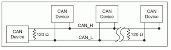
Same thing.. hmm.. Oh the 120R resistor jumpers. The CAN network uses differential signaling and require terminating resistors to insure a recessive level once the signal returns to zero as well as to help absorb any reflections in the transmission. BY all rights you should also include twisted pair for a fixed impedance.
After I removed the resistors and rebooted the car, (turned the key off and on), the bus error went away.
Different voices in each ear.
I then opened two separate shell windows to the Raspberry Pi and ran cansniffer in each one.
#on screen 1
cansniffer -c can0
#on screen 2
cansniffer -c can1and bang!
I was able to observe traffic from the two different data busses. Now there is a lot there to take in. If you slow down the movie, you will notice that the output from cansniffer on the left window has the following line
01000 | 3E6 | 0B 31 0FThe first item (01000) is the frame number . The second item (3E6) is the frame ID. It turn out that on this particular model of Wrangler, the code 0x3EF is a message from that broadcasts the current time so that among other things the radio can display it. The 0B 31 0F is hex for 11 49 15, 11:49:15 AM. You will notice that as that value increments, the changes show in red.
Interesting thing: On the Wrangler the time frame is broadcast by the Sentry Key Remote Entry Module or as its affectionally know as SKREEM. It’s the thing that listens for command from the key FOB (Finger Operated Button) to remotely lock and unlock the door(s).
It also turns out that you can tell the SKREEM to set the time by sending a 0x2E9 frame on the bus.
#set the clock to 18:00:00
cansend can0 2E9#03120800
The frames on the right side are coming from the the GM motor and they have a completely different set of frame IDs as the Wrangler. That information is detailed in the Platform to Powertrain Electrical Interface Specification, GMW8762. Which happens to be available to the public, unlike the Chrysler codes which you will have to reverse engineer. But thats another topic for a later chapter.
We caught the bus, What now?
Just like a dog chasing a bus, what do we do next? Well as I mentioned above, some of the protocol is documented (GMLAN) and others we have to reverse engineer. In the next episode we will talk about how we go about figuring out what packets mean what.
I tell ya, my dog is lazy. He don't chase cars. He sits on the curb and takes down license plate numbers. —Rodney Dangerfield