
Kicking Zeus's ass
Dealing with the fun of rural power spikes and lightning strikes.

I love living in rural Arkansas. It certainly has challenges, and like anything else, there’s a learning curve. We get some awesome storms, especially lightning storms. One thing I hadn’t expected was the havoc that these storms wreak on electrical systems through the power grid.
I’ve written about how lightning works — but figuring out how it jacks up the grid took some extra digging. As far as I can tell, the damage originates from three primary sources:
Utility Reclosers Events - These automatic breakers detect faults (tree branches, lightning hits, etc.) and attempt to restore power by closing the circuit multiple times.
Sudden voltage spikes during reclosing
High inrush current as loads reconnect
Multiple fast transients in short intervals
Line ringing and noise between attempts
Lightning-Induced Surges - Even without a direct strike, lightning near power lines can induce massive voltage surges through electromagnetic coupling. Typically, these surges are:
Very fast (nanosecond rise times)
Very high energy (multiple kilovolts)
Capable of arcing across PCB traces or vaporizing components
Utility Grid Switching and Load Transients - The utility grid performs switching operations to balance load, engage capacitor banks, and manage transformer taps. These actions can generate:
Differential-mode voltage jumps
Common-mode noise bursts
Harmonics and line distortion
Load reconnect surges
Post-Mortem: Power Supply Failure
Put on your CSI hat, and let’s look at how the power grid caused some cool catastrophic damage to a piece of equipment I used in one of my early irrigation system prototypes.
I used a standard low-voltage transformer to produce 24V AC for the sprinkler controllers connected to a cheap AC 10-24VAC to 5V DC power module I picked up on Amazon.
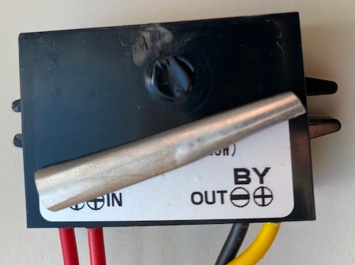
This device failed during or shortly after a storm involving lightning activity and probable utility line disturbance. No upstream line filter or surge suppressor was present. Examining the device, I found:
Localized melting of enclosure plastic
Some trace vaporization from the internal arc path
Complete functional failure (no voltage output)
The unit showed no external signs of gradual failure; rather, the damage suggests a sudden, high-energy event. The arc location indicates the failure began on the input stage. There was no evidence of a load-side short or fault; failure was upstream.
I replaced the unit, and it worked till the next big storm, which caused a similar failure, this time shorting the transformer, and it also managed to take out the Raspberry Pi Zero and one of the I²C devices attached.
The bottom line is that the nature of the damage was consistent with high-voltage transients common in overhead utility systems during storm conditions.
Why don’t you just buy a surge suppressor?
Yeah, that’s nice. But they are designed mostly for use in well-regulated, indoor environments — not the chaotic grid conditions of rural areas. They rely heavily on metal-oxide varistors (aka MOVs), which are cheap, fast to degrade, and generally insufficient for repeated, high-energy events like lightning or recloser surges. Typically, they can handle around 600 joules, which is okay for minor spikes, but it won’t last—or even survive—a big rural surge.
The truth is, they are designed to reduce EMI getting back into the grid, not protect from the grid.
The ZeusFilter 1.0
So how can we build something better? Sure, we can. We are supposed to be engineers!
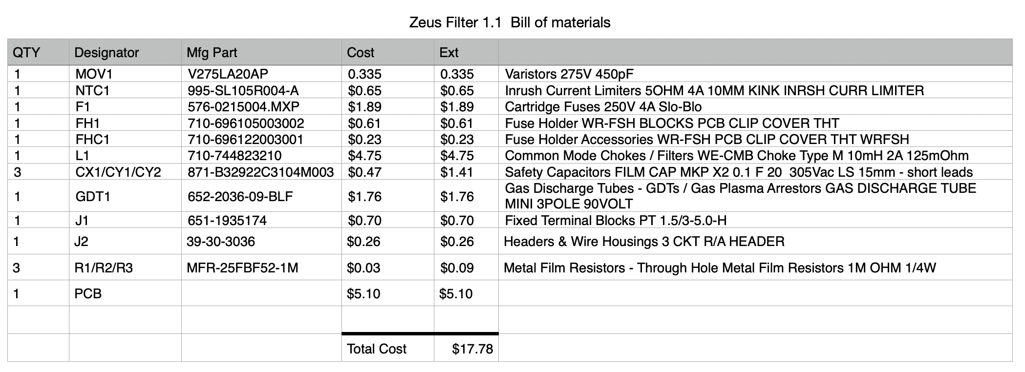
Let’s start with a simple 3-position terminal block for our prototype circuit that accepts standard AC grid input: L (Line), N (Neutral), and Ground. We’ll even add an extra-large ground screw that we can attach to an optional ground rod (be careful of ground loops).
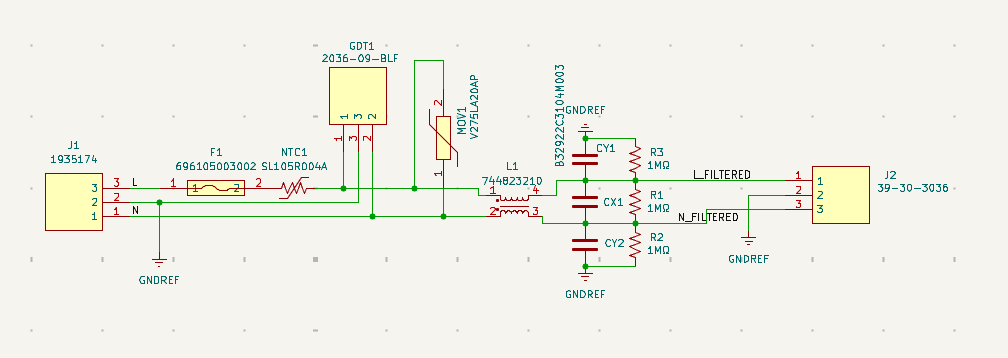
The first thing we do is to go through a 4A Slow-Blow Fuse for short-circuit and overload protection. I even put it in a nice fuse holder.
We follow that up with an SL105R004A thermistor. This device limits inrush current during power-on. As it warms up, its resistance decreases, reducing power loss in normal operation.
Next up, I added a Bourns 2036-09-BLF 3-electrode gas discharge tube, between the Hot, Neutral line, and Ground. The tube triggers at ~200V to dump high-energy surges directly to earth ground. This is for the lightning-level events and major faults.
I would also suggest an MOV to clamp fast voltage spikes and absorb the medium-energy transients from reclosers or grid switching. For my first attempt, I used a B72220S0271K101 (275VAC MOV), but in retrospect, I think I will use a Littelfuse V275LA20AP. It has higher surge energy capacity (220J vs ~120J). This will give it a little more lifespan and durability. Since it has the same physical footprint on the PCB, it's a no-brainer.
Further into the circuit, I added a Wurth 744823210 10mH common-mode choke. This will block the EMI noise that appears identically on both Line & Neutral. This is the kind of chatter you get from utility reclosers. The two windings on the ferrite core cancel out unwanted high-frequency noise (common-mode), but it lets the 60 Hz AC pass unaffected.
Before we get to the output, I also added a series of class X and Y “safety capacitors” to filter any leftover high-frequency crap to ground or cancel it across the line. They are called safety capacitors because they are designed to fail in a way that protects people and equipment.
To be safe, I added a few 1MΩ, 0.25W resistors across the CX1/CY1-2 capacitors to discharge them after AC is removed. This will make storing and working safer once the power is removed. Otherwise, there is a high chance of getting zapped on the output line.
We end up with a discrete AC line conditioning circuit combining overvoltage protection, inrush limiting, and EMI/RFI filtering into a compact single-layer PCB. It should give my upstream circuits clean and stable AC input under real-world conditions, including the grid switching, lightning surges, and automatic recloser events we get out here.
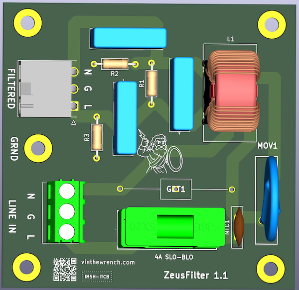
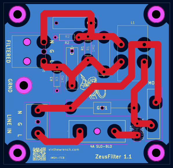
In the time since I wrote this article, I mad a few revisions to the board. High on my list was the addition of drain resistors R1-3. I also changed the output connector
Handing the Spikes
Here is what I predict how the filter will handle the various grid events:
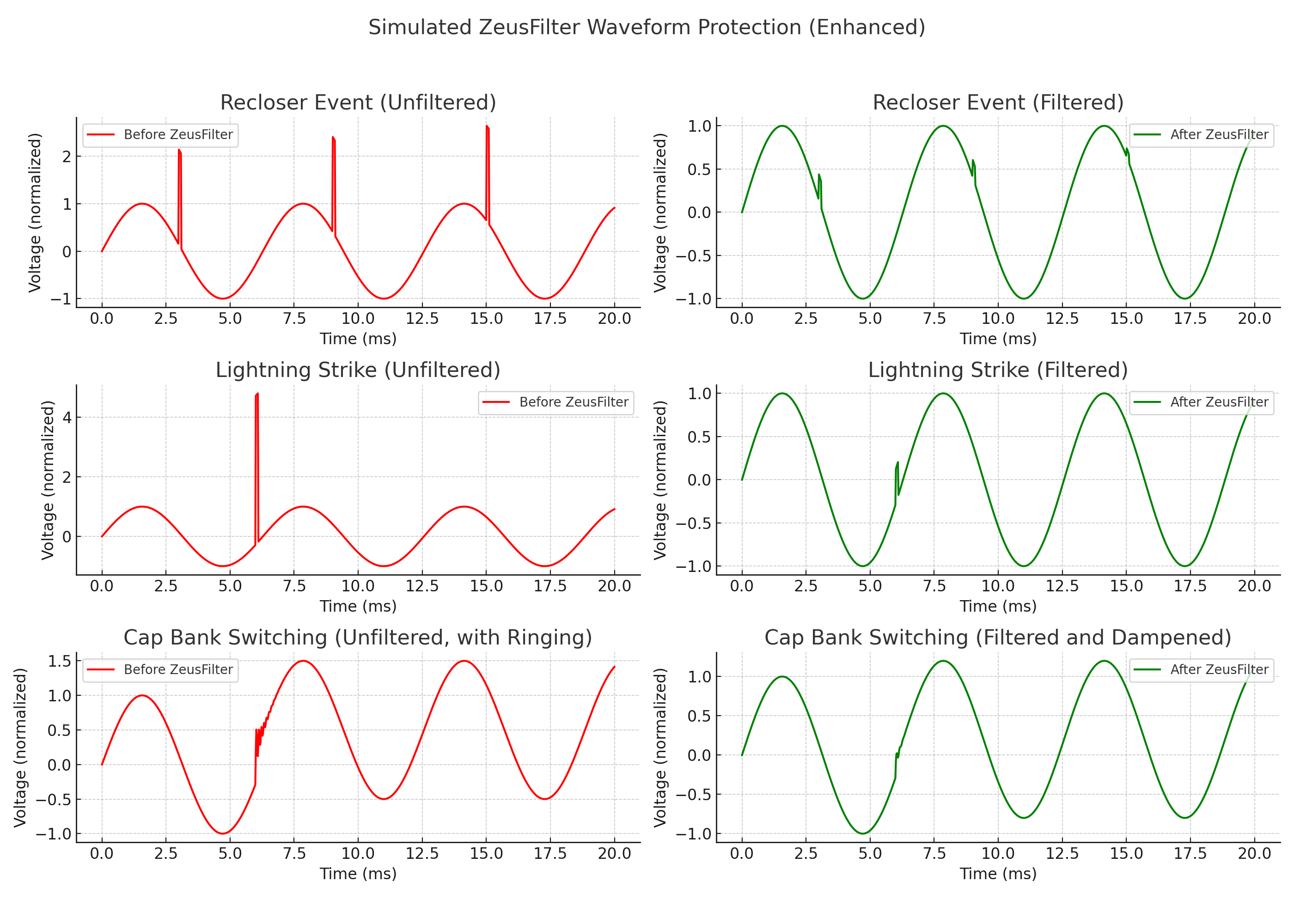
As soon as I get some boards built up, I plan to put this device between the AC power coming into my controller and the power supply. Most likely, mount the PC card on a DIN card holder and then 3D print a box to cover the unit. The AC out will feed something like a Mean Well DRC-40A or DRC-100A power supply with a built-in battery charger to act as a UPS.
I will post an update in another article describing the UPS system when all this works together.
YOU HAVE BEEN WARNED
⚠️ WARNING: HIGH VOLTAGE FILTER DESIGN ⚠️

The ZeusFilter operates directly on AC Mains — 120 to 240V — and is NOT hobbyist-friendly.

This is real-world, line-voltage gear built to survive lightning strikes, grid surges, and utility chaos.

Improper handling can result in electric shock, fire, or death.

This is not a breadboard project.

If you don’t fully understand:
 - Line vs. Neutral vs. Earth
 - What happens when a MOV fails
 - Why safety caps are a thing
 - How to test with the power OFF...

...then step back, read more, or build this under supervision.

🔥 YOU’VE BEEN WARNED. Zeus doesn’t do second chances. 🔥
That said, I was planning to post the KiCad online, but the lawyer in my brain says maybe not.

This post is part of the Off-Grid Farm Automation with Raspberry Pi series — a full DIY walkthrough of building a self-hosted system for sensors, valves, and automation, no cloud required.
The Zeus board is still evolving. I’ve put a lot of thought into practical protection, but I’m not claiming it solves *every* problem. There’s always going to be some insane corner case where Zeus gets his thunderbolt through. I’m aiming for solid, affordable defense against the most common grid-born nasties — not lab-grade immunity or mythical indestructibility. Suggestions welcome, but keep it grounded.
Thanks to a hackaday contributor, I might update the MOV to something like a TMOV20RP275E THERMALLY PROTECTED VARISTOR