
Raspberry Pi Internet of Things - part 18
Smart Power Switch and Shutdown for Raspberry Pi Farm Projects

This article is part of the Off-Grid Farm Automation with Raspberry Pi series, where we build resilient, real-world systems step by step. In this section, we tackle one of the most overlooked problems: power management. A Raspberry Pi running irrigation valves, sensors, or other farm devices can’t just be unplugged — it needs to handle power failures gracefully. With UPS-style supplies like the Mean Well DRC series, we’ll design a smart power switch and safe shutdown circuit that keeps the Pi alive long enough to finish irrigation cycles during outages, then powers down cleanly to conserve battery until utility service returns.
I first explored these ideas in my Raspberry Pi Car Radio project, where I needed to solve the problem of shutting off the Pi once the car was off and secured. That led to a safe shutoff switch that allowed the Pi to signal when it was ready to cut power, and later a CAN-bus wake circuit that brought the system back to life automatically when the vehicle network became active.
Now, those same principles carry over to the farm — but instead of ignition keys and CAN traffic, the triggers are utility power, irrigation schedules, and a UPS supply that gives just enough time to finish watering before shutting down to conserve battery
Design Goals
On the farm, the requirements shift: the Pi isn’t just running a display or a head unit, it’s coordinating pumps, valves, and peripherals that draw far more power and need to behave predictably when the grid winks out. That means the power system for this motherboard has a few non-negotiable goals:
Coordinated shutdown — finish the work in progress, then power off safely.
Smart wake-up — come back up cleanly when power returns.
Protect the battery — avoid slow parasitic drain when the system should be off.
The Power Source: DRC UPS Supply
In the car radio project, the Pi lived on an alternator and a starter battery. Out on the farm, the setup is a little different: instead of an alternator under the hood, we’ve got a UPS-style supply with an integrated charger. That’s where the Mean Well DRC series comes in.
Mean Well actually markets these as security power supplies — designed for alarm panels, access control, and other gear that can’t afford to drop out when the grid blinks.
In my own battle with dirty rural power and spikes, these supplies have proven steady. They ride through brownouts, switch cleanly to battery, and hand the Pi just enough warning to shut down gracefully when the charge finally runs out.
The DRC delivers regulated 12V to the load, keeps a lead-acid or LiFePO₄ battery topped up, and automatically switches over when utility power fails. In short, it’s a small UPS built for DIN-rail, with the bonus of alarm outputs that tell you what’s happening inside.
All the models work the same way — AC-DC, single-output, with integrated charger and UPS function — and they come in sizes from 40 W up to 180 W. The differences are just in how much load they can handle.
Most important for us, the spec sheet spells out two status signals:
AC OK — low when utility power is present, high (open) when the line fails.
Battery Low — low when the battery is below cutoff (about 11V in a 12V system), high when it’s still healthy.
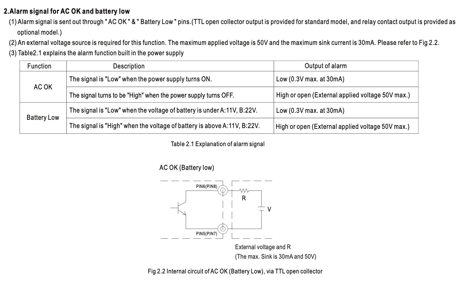
Those lines give the Pi situational awareness: whether it’s on grid power or running from backup, and how much time is left before things go dark.
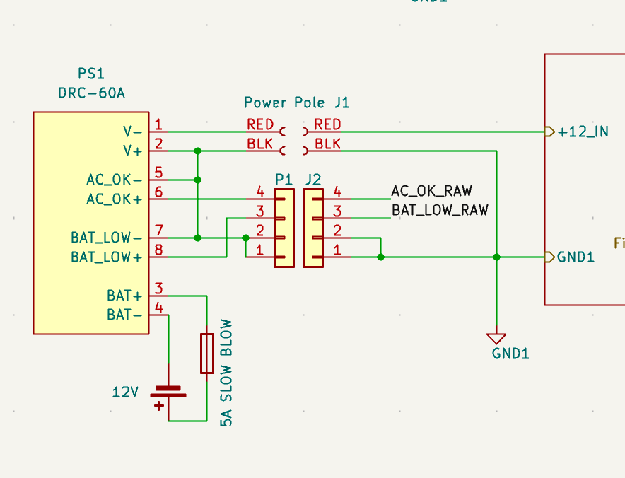
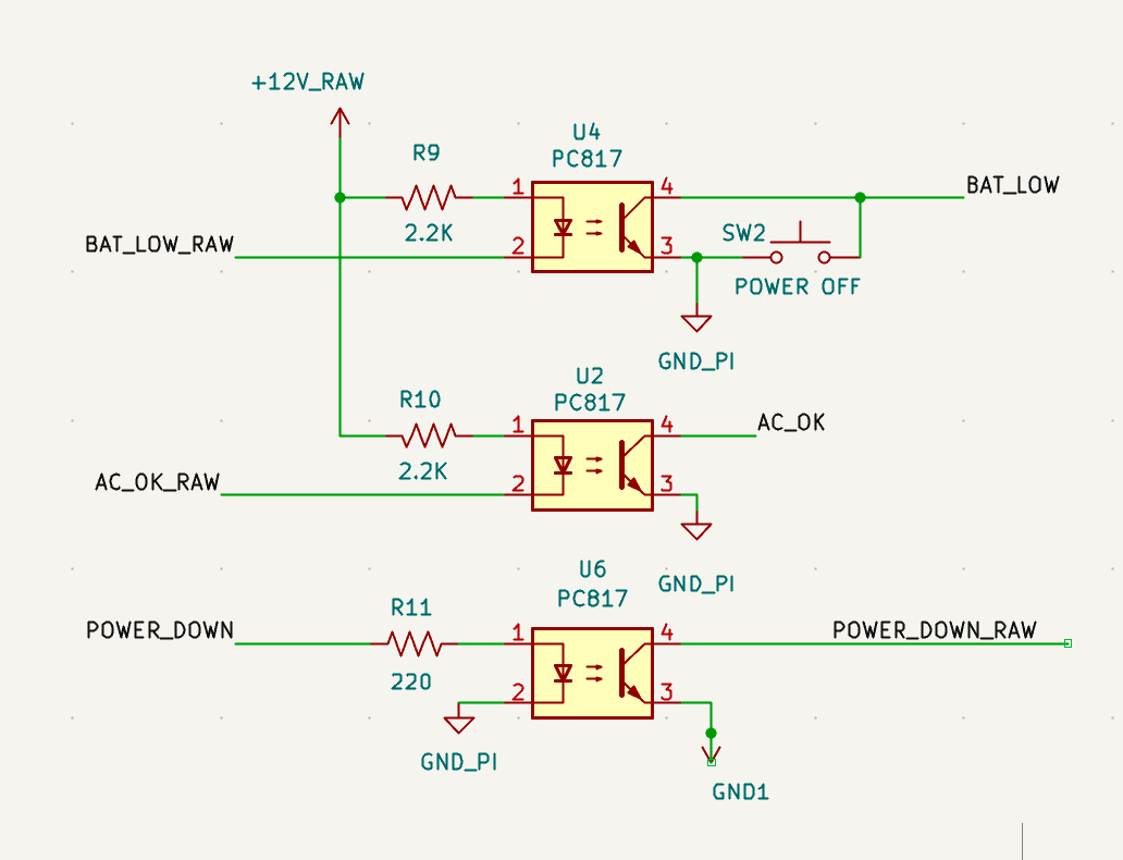
⚠️ Note on Signal Isolation
Although the datasheet doesn’t spell it out, both alarm signals share their negative side with the supply’s 12-volt return. That’s fine for most alarm-panel applications, but in our farm system the Pi is powered through an isolated DC/DC converter for its 5V output. To keep that isolation intact, the alarm lines also need to be isolated before they touch the Pi’s GPIO. We’ll circle back to how that’s handled later in the design.
Why a Latching Relay Still Makes Sense
Back in my car radio project, I stumbled on a better fit: a bi-stable latching relay originally used as a glow plug controller in older Mercedes and BMW diesels — specifically the Hella 0025428119 / 933364027. Built to survive under-hood heat and vibration, it turned out to be perfect for low-power, high-reliability switching. Once latched, the relay requires no holding current — only a short SET or RESET pulse — which eliminates parasitic drain on a standby battery.
💡 Part Numbers Explained
You’ll sometimes see this relay listed under the Mercedes-Benz OEM number 0025428119, since it was used as a glow plug controller in older diesel models. In Hella’s own catalog, it’s 933364027 — the same 12-volt bistable relay, just a different label.
I looked at MOSFETs, I looked at standard relays — but both came with baggage. MOSFETs leak, need extra protection, and hate dirty inductive loads. Standard relays draw coil current the whole time they’re on.
The latching relay, by contrast, is rugged, efficient, and simple. Once it clicks, it stays there — no trickle current, no leakage path, no phantom loads. When it’s off, it’s really off. And when it’s on, it will happily switch the entire +12-volt supply without blinking, even when that power is shared across multiple devices. That makes it a natural choice for farm automation, where the priorities are reliability, low standby drain, and the ability to shrug off whatever noise or abuse the environment throws at it.
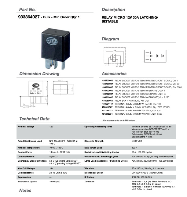
This catalog page (Hella Electrics, 2012, p. 13) shows the full spec: a 30 A bistable relay with SET/RESET coils, designed for high-current loads and zero standby drain. If it can keep diesel glow plugs alive through harsh winters, it can certainly manage a farm Raspberry Pi project without breaking a sweat.
Driving the Relay
The Hella latching relay is the muscle behind this whole power system. It doesn’t behave like an ordinary relay with a single coil that has to be held on. Instead, it has two coils: one to SET the relay and one to RESET it. A quick pulse to either coil is all it takes, and once the contacts have moved, the relay stays put with no standby current at all. That’s why it works so well in places where efficiency and reliability matter — whether it’s under the hood of a diesel Mercedes or sitting in the middle of a farm control board.
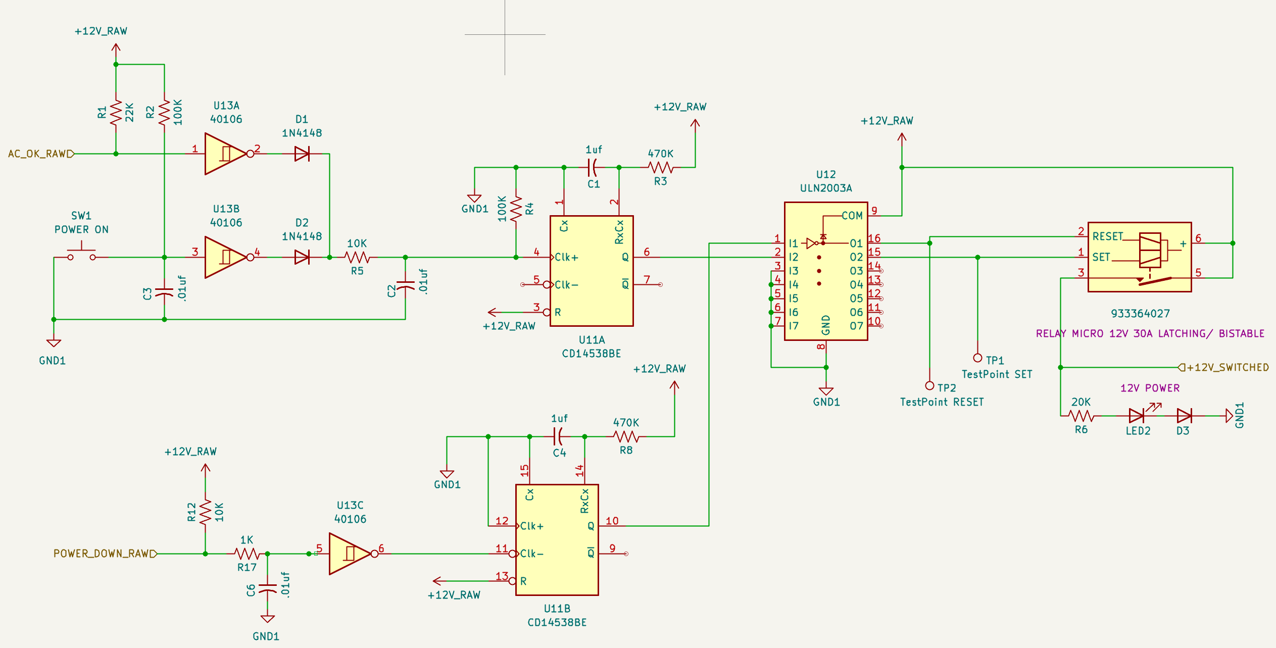
When the DRC power supply comes up and signals that it’s healthy, it drives a line called AC_OK_RAW. That signal isn’t guaranteed to be pretty — long cable, possible chatter — so it’s tamed first. A resistor and capacitor slow down any hash, and a 40106 Schmitt trigger snaps it into a clean digital edge. The manual POWER_ON button goes through the same cleanup path: local pull-up, a little RC to kill bounce, and into another 40106. Both clean edges are diode-OR’d together so either the supply’s AC_OK or a button press can start the system.
That OR’d edge runs through one more small RC network before hitting one half of the CD14538BE dual one-shot. The 4538 turns whatever came in — ragged, short, or bouncy — into a single, solid half-second pulse. That pulse drives a channel of the ULN2003A, which sinks the SET coil on the latching relay. These coils don’t want to be held on continuously — they only need a sharp, well-defined kick. Long enough to guarantee the relay trips, short enough to avoid wasted power or unnecessary coil stress.
Power-off starts at the Pi itself. When you run sudo shutdown, the Pi’s gpio-poweroff overlay pulls its POWER_DOWN line low. That low goes through an optocoupler (PC817) to keep the Pi isolated from the 12-volt world. On the opto’s output, a pull-up and a 40106 clean the transition, producing a sharp falling edge.
That edge feeds the second half of the CD14538BE, which generates another half-second pulse — this time to the RESET coil of the relay. The ULN2003A sinks that coil’s current, the relay unlatches, and power to the Pi is cut. Even if the 12-volt supply is still present, the Pi can shut itself off cleanly and stay off until AC_OK or the manual button gives it a fresh “on” signal.
⚡Back EMF: why you always need a clamp
If you’ve never actually seen what a relay coil does when you cut the current, Dave Jones has a great demo on his EEVblog: Back EMF in Relay Coils. He shows how a coil can spit out hundreds of volts when the magnetic field collapses, and why we tame that with flyback diodes or snubbers. He even digs into the downsides of simple diode clamping and shows a couple of weird, rarely-seen effects. Worth a watch if you want to see the physics behind why I am using the ULN2003A and it’s built in clamp diodes.
Handshake Between Pi and Power
The relay and its drivers are just the muscle — they only work because the Pi and the power hardware speak a simple language. The sequence goes like this:
The DRC supply reports status: one line (AC_OK) shows when utility power is present, another (BAT_LOW) warns when the backup battery is nearly spent.
These signals pass through optocouplers before they reach the Pi, keeping the 5V side electrically isolated from the noisy 12V side.
The Pi monitors those inputs, finishes its current tasks, and then asserts POWER_DOWN when it’s safe to shut off.
Finally, when the Pi finishes a clean shutdown, it asserts POWER_DOWN through an optocoupler. On the 12-volt side, the ULN2003A sinks the RESET coil for a half-second pulse from the CD14538BE. The SET pulse comes from AC_OK or the Power On button via the other half of the 4538.
The end result is simple and predictable: the supply reports what’s happening, the Pi decides when it’s safe, and the relay enforces the outcome. Just a handful of isolated signals turn the Pi into a coordinated part of the power system.
Power On
The normal trigger for startup is the AC_OK_RAW signal from the DRC supply. When utility power is present, that line goes low, the circuit responds with a SET pulse to the latching relay, and the 12V supply comes alive. The Pi boots, peripherals power up, and the system is ready for work.
The Power ON button is purely a convenience. It can’t override the DRC — if the supply isn’t producing 12V, the button won’t do anything. But once AC is present and the supply is alive, pressing it injects a manual SET pulse into the relay driver. That gives you a quick way to wake the system and boot the Pi without waiting for logic signals or software.
⚠️ Side Note on DRC Behavior
The DRC is a failover power system. It only comes alive when AC is present — that initial line power is what starts the supply and begins charging the battery. Once running, the DRC will seamlessly hand off to the battery if AC fails, and it will stay in that mode until the battery reaches cutoff. At that point, the supply stops delivering DC. Simply swapping or recharging the battery won’t bring it back online; AC has to return first to wake the system again.
Power Off
Shutting down is the harder part. You can’t just yank power from a Raspberry Pi and hope for the best — not when it’s running a database of soil readings or driving irrigation valves. That’s why the Pi has to be in charge of its own exit.
When AC_OK_RAW drops and the system is running on battery, the clock is ticking. If the battery eventually falls below the BAT_LOW_RAW threshold, the supply signals that it’s time to quit. With a large enough backup battery, the system can ride through outages for hours — even finish a full irrigation schedule — before the Pi finally gives the shutdown command.
The Pi sees the warning, finishes whatever task it’s in the middle of, and asserts the POWER_DOWN line once the file system is clean and the software is safely parked. That signal tells the circuit to simulate a Battery Low event, which in turn triggers the relay to cut 12V in a controlled, predictable way.
There’s also a Power OFF button for manual control. Pressing it makes the Pi go through the same sequence — raise the shutdown flag, simulate a battery low, and only then let the hardware drop power. It’s not an emergency stop — more like a clean ignition key for software-controlled hardware.
⚙️ Implementation Note
On the Pi side, we mapped BAT_LOW and POWER_DOWN to GPIO 23 and 25. They could have been almost any pins — these just made PCB layout easier. To enable the behavior, add the following dtoverlay lines to /boot/firmware/config.txt:
; BAT_LOW - INPUT
dtoverlay=gpio-shutdown,gpio_pin=23,active_low=1,gpio_pull=up

; POWER_DOWN - OUTPUT
dtoverlay=gpio-poweroff,gpiopin=25
This way, the hardware handshake lines map directly into Linux’s shutdown and power-off behavior without extra software glue.
💡 Alternate Setup with HAT EEPROM
Some Pi add-on boards use an I²C EEPROM (like an AT24C32) to hold a Device Tree overlay so GPIOs auto-configure at boot — still supported, but harder to change later. See the Raspberry Pi HAT spec.
Getting from 12V to 5V for the Pi
The DRC provides a solid 12V output, but the Pi still expects a regulated 5V supply. Not every system needs galvanic isolation — a hard electrical barrier between the Pi’s ground and the 12V side. If you’ve got long wiring runs, pumps, or motors sharing that same 12V line, isolation keeps the noise, spikes, and ground loops from ever reaching the Pi. In a clean, compact setup with short wiring and no big inductive loads, isolation isn’t strictly necessary and just adds cost.
That’s why the motherboard was designed with a dual-footprint option: it accepts either an isolated Traco THN 30WIR or a non-isolated Pololu D36V50F5 in the same slot.
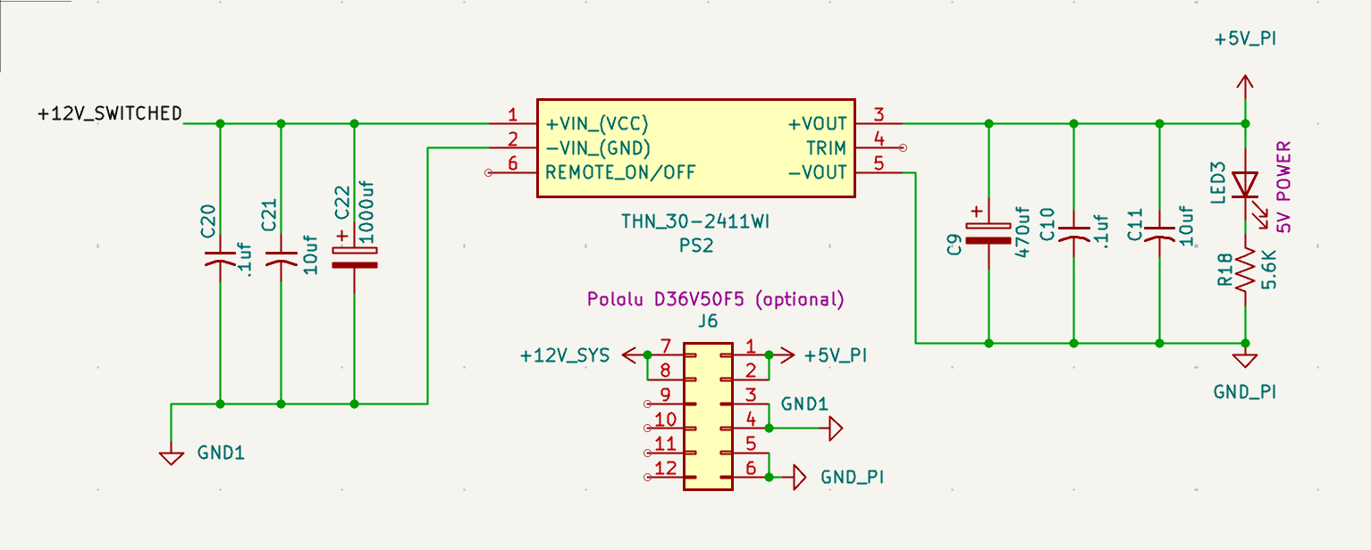
Isolated option: The Traco THN 30WIR. This is a railway-grade DC/DC converter, designed for the kind of hostile conditions you’d find in locomotives and rolling stock. It handles wide input swings, shrugs off transients, and stays efficient across extremes. With up to 92% efficiency, it can deliver full output from –40 °C to +65 °C without derating or extra cooling (depending on the model). It isn’t cheap, but if you’re wiring across barns or running long outdoor lines, that kind of bulletproof design pays off.
Non-isolated option: The Pololu D36V50F5. This is an excellent regulator — compact, affordable, and capable of delivering up to 5A at 5V straight from the 12V supply. The only tradeoff is that it’s not isolated, so it ties the Pi’s ground directly to the 12V side. For short, tidy wiring in a controlled environment, that’s usually not an issue.
With this layout, the Pi never sees raw 12V — only a clean, regulated 5V supply. You can match the build to the environment: railway-grade isolation when needed, or efficient simplicity when it isn’t.
How This Differs from Off-the-Shelf Pi Power Boards
Add-on boards like PiJuice, Witty Pi, and Waveshare UPS HAT handle backup power and shutdown for a single Pi. They’re polished, well-supported solutions designed for projects where the Pi is the only load and the runtime needs are modest.
This design is different. It’s built into a full motherboard the Pi plugs into, with the ability to manage radios, sensors, and other hardware from the same 12-volt source. Instead of a small lithium pack, it works with an external battery sized for the job and coordinates with a rugged Mean Well DRC supply.
Where the HATs keep a Pi alive, this setup makes the Pi part of a larger, reliable system.
Bringing It All Together
Power management isn’t a side feature — it’s what makes a Raspberry Pi act like part of a system instead of a hobby board hanging on the end of a wire. With a DRC supply handling AC failover, a latching relay doing the heavy lifting, and a handful of signals traded between hardware and software, the Pi can finish its work, shut itself down cleanly, and wait for the grid to return.

On the farm, that means irrigation cycles complete instead of cutting out halfway. It means batteries last instead of being bled dry. Most of all, it means the Pi becomes a reliable partner in automation — something you can trust in the field, not just on the bench.
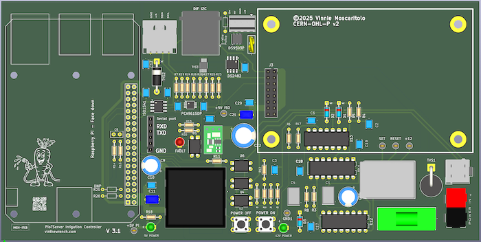
This design is just one piece of the bigger picture. In a later article, we’ll step back for an inside look at a hands-on build: the custom motherboard that ties it all together — power, I²C, 1-Wire, and sensor integration. It’s the backbone that makes off-grid automation practical.
This post is part of the Off-Grid Farm Automation with Raspberry Pi series — a full DIY walkthrough of building a self-hosted system for sensors, valves, and automation, no cloud required.
Note -- I updated this logic -- read here --https://www.vinthewrench.com/p/chasing-raspberry-pi-power-management
Imagine that I found a bunch of mistakes I don't like and I'm redesigning this power on circuit. For now I'll use simple logic but later rev. I'll probably use a pic