
The Great Pumpkin patch pump
Pumpkin patch irrigation project

This is the third article in my series about our move to Arkansas. In our previous adventure, I discussed how we got water for our crop beds. This article addresses a slightly different problem.
While this is still a work in progress, it has supplied us with water for one growing season so far.
Pumping water from the creek.
Let’s start with the problem statement. We want to supply enough water to feed a pumpkin patch for our market garden. If we assume that pumpkins typically need somewhere like 2” to 3” of rainfall a week, we can estimate our needs based on the number of plants we put in.
The closest water source to the pumpkins is a creek. We wanted to do things properly, so we contacted the various state agencies to figure out what the regulatory framework was like. What we found was very favorable. We were informed that because the creek runs through our property and since our location is close to the headwaters, we were allowed to pump water from it as long as we did not exceed a certain amount yearly per acre-foot. In that case, we would need to register so that the Corp of Engineers can allocate enough release from the reservoir downstream. Did I mention why I moved to Arkansas in the first place?
We scouted for an optimal location for water pickup. I wasn’t quite sure if I could pump enough water to provide pressure to reach the pumpkin field, so I chose to place a water tank at the edge of the field. The distance to the creek was less than 60’, and the rise to where I would place the pump was about 15’. This gave me the parameters I needed to design a pump, storage, and distribution system.
The Parts
We are a professional market garden, and I have learned over the years not to skimp on the quality of parts. I also didn’t want to spend any time replacing stuff each year. Here is a short list of the significant items in the system.
Snyder Industries 2500-Gallons Plastic Black Water Storage Tank
Various PVC fittings and valves
Water Tank
While cruising through Lowes' parking lot, I noticed that they had the same 2500-gallon water tank that I used in our old Oregon home to store water for fire suppression and gardening. These Snyder Industries / Norwesco tanks are designed to store potable water. They ship with a 2” drain and 1.5” upper fitting.
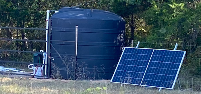
I found a suitable location for the tank. It was high enough above the floodplain that the ground did not need much preparation. To be safe, I lined the ground with a heavy-duty tarp we picked from Billboard Vinyls.
Once the tank was in place, I sunk a 4x4 post to hold the pipe feeding the inlet at the top of the tank. I employed a trick I learned from the local electrical linemen: Rather than filling the post hole with cement; I filled it with Sika PostFix polyurethane resin. This stuff is pretty amazing, but make sure you read and follow the instructions carefully. It works quickly.
I then built a base to hold the pump box and plumbed the lines to the tank fill and drain.
Incidentally, If you look at the picture below, you will see a large valve and inlet on the left-hand side of the post. This allowed me to fill the tank using a trash-pump. I used this system before I had the JET pump system in place.
There is also another large valve and connecter on the drain side, which would allow me to drain the tank quickly and possibly use it for firefighting.
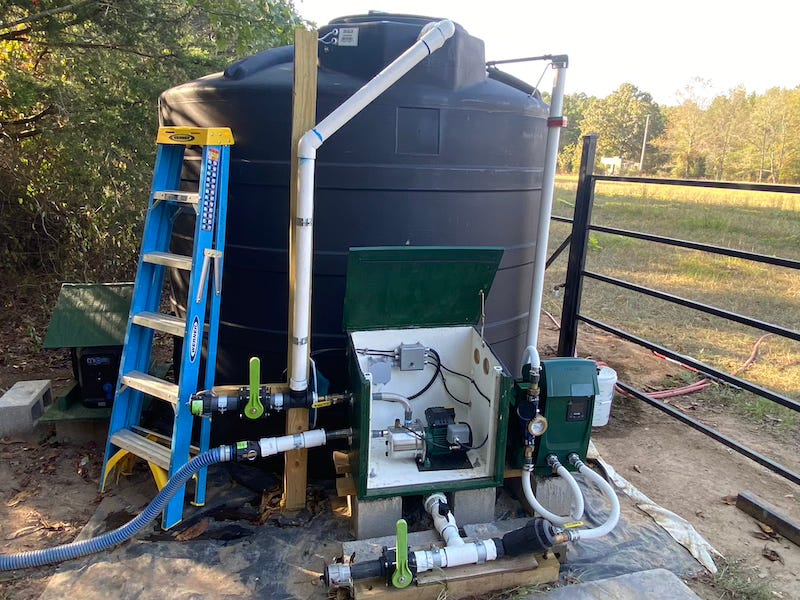
I also fabricated a water-resistant box using 3/4 marine plywood with a sliding access panel to house the JET pump and electrical controls.
DAB JET Pump
Given the distance and elevation, I calculated that I would require a 3/4 HP pump to provide sufficient water flow to the tank. I reached out to the very knowledgeable folks at Rain Harvesting Supplies and explained my predicament. I was looking for a highly reliable pump that was self-priming and could also work in the presence of air bubbles. It also needed to handle any sand particles that the creek filter might miss.
They turned me on the JET SS 75 made by DAB. This pump was made for serious use. It had a wide temperature range, a stainless steel body, and was clearly designed for rugged environments. It could also be configured for 110 or 220v.
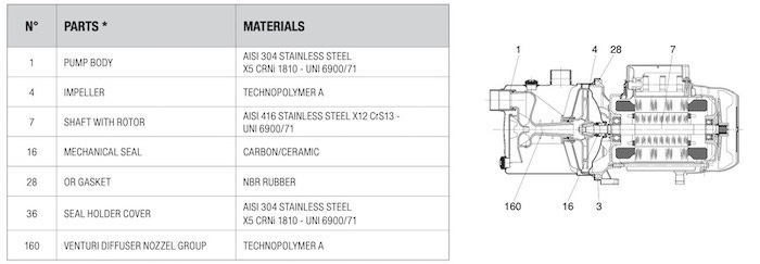
I spent some time digging through the detailed specifications and the meticulous notes in the DAB dataroom. These pumps are high quality, certainly not some cheap China knockoff. While running power requirements were rated at 115v at 10.3 A, I was more concerned with the locked rotor current. Since I plan to use solar power for this system, I had to size the inverter appropriately.
By the way, self-priming doesn’t mean starting from a dry pump housing; you do need to have some water in the system. This is one of the reasons I built the standpipe so tall on the inlet side. Even if the input hose has air in it, water will fill the housing from above.
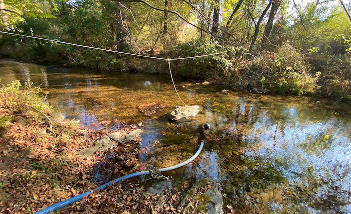
The Creek Pickup
I ran about 60’ of 2” suction hose from the pump inlet to the creek, where I hooked it up to a Floating Intake Filter. A check valve after the filter prevents water from flowing back from the pump when it is not running. I added another check valve further up the line, too, because I was still finding air bubbles. Did I say this was a work in progress?
If you look at the photo above of the creek, you will also notice that I ran a stainless steel guyline to prevent the filter from washing away during rainstorms.

It took a little bit of fooling around at the beginning to get some water in the inlet hose.
In addition to the inlet filter, I also added a 2” Polypropylene Y Strainer on the drain side of the tank to keep sand out of the pressure pump and any irrigation we build in down the line.
The Pressure Booster
Without sufficient height, a gravity-drained water tank itself can not provide enough water pressure for anything useful. To drive the hoses or pipes out to the pumpkins will require a pressure booster pump. But these systems are not really that easy to design properly. They require switches to detect when there is a demand for water and also a safety system to prevent running while the pump is dry. In our circumstance, it was also useful to track water usage.
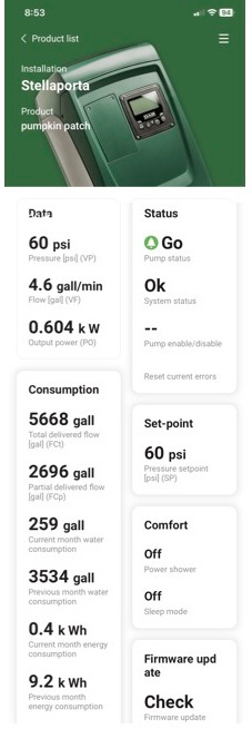
I was concurrently building many other projects and didn’t want to spend too much time designing the booster pump, so I chose to use a premade solution. I installed a DAB ESYBOX Mini 3 unit. The ESYBOX is a complete, integrated electronic constant water pressure booster system.
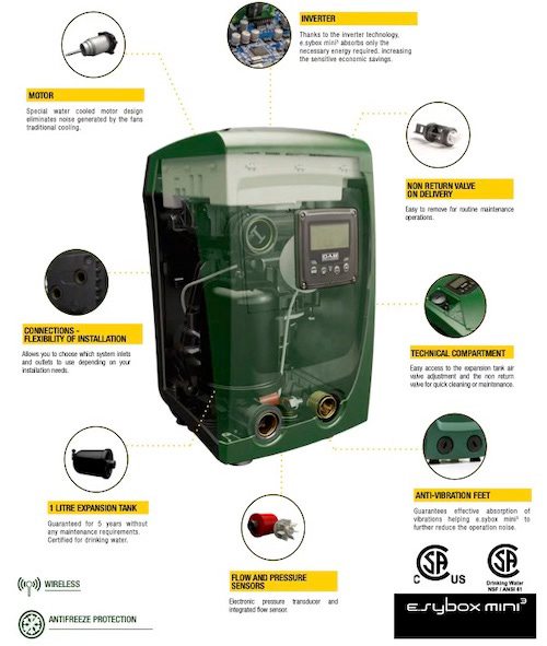
Some of the advantages of the ESYBOX are that it has a wide temperature range and can be installed outside; it also has filters to keep bugs from crawling in. The ESYBOX also has a wireless system that allows you to set up, control, and debug remotely.
It certainly wasn’t cheap, but it worked correctly the first time and can be used for other projects later. I mounted it in such a way that it would be easy to remove it for the winter.
The Float Switches
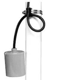
To control the tank JET pump, I needed to build a circuit to turn it on when the tank water level when it is too low and turn it off when it is full. Commonly, this is accomplished with a standard liquid-level tank float switch attached to a vertical pipe in the tank. Set it to float height near where you want the pump to stop filling the tank. If you plan to do this, note that there is even a special cable clamp available to make things easier.
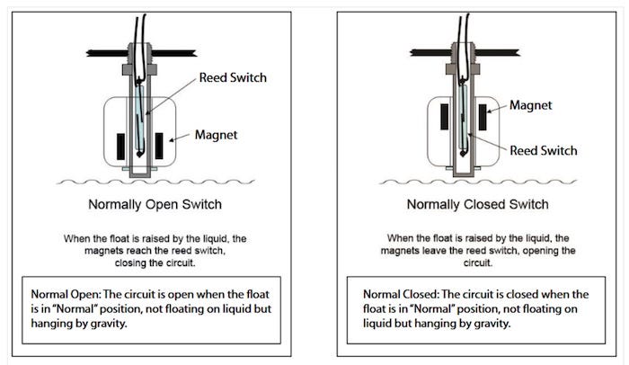
Tank float switches electrically fall into two categories: Normally Open (NO) and Normally Closed (NC). The terminology is always confusing, and it seems that I have to relearn this every time I do it. Here is the rule of thumb. The manufacturers consider the float to be in the normal position when it is not floating. Therefore, a Normally Closed (NC) float conducts electricity when the waterline is below the float and breaks it when the device floats. Conversely, a Normally Open (NO) float conducts electricity when the waterline forces the device to float and breaks the circuit when the device hangs down.
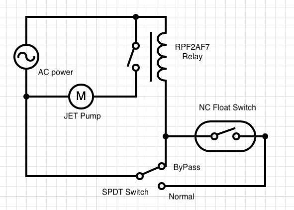
Now that we understand that, we can use this to control the pump system. For the tank fill JET pump, we wire the motor in series with a Normally Closed (NC) switch.
As a safety precaution, I want to prevent the ESYBOX pump that provides water pressure to the crops from running if the tank gets too low. I wired that pump in series with a Normally Open (NO) switch mounted near the bottom of the tank.
One more complication: typically, the float switches can not handle a lot of current. I would like to prevent the float contacts from burning out over time, so I added a small relay, for example, an RPF2AF7, in the circuit so that a minimal amount of current goes through the contacts.
How much water is in the tank?
While the float system will turn on and off the pumps, one of the questions left unanswered is what is the tank level. It would be useful to have a visual indication. A great and reliable solution to this problem is the Liquidator 2 Tank Level Gauge from Yaktek Industries. This ingenious device uses a internal tank float and a series of pullies and a counterweight to lift a mechaincal gauge indicator on pipe mounted by the tank.
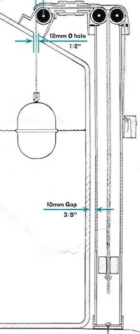
The Liquidator is fairly easy to setup, but it does require you to have visual access to the tank. In the future, I will probably build a project using the TL231 pressure sensor that I used previously in my article about how to remotely measure cistern water level.
Solar Power System
Initially, I powered the pump systems- with a small gas-powered Honda inverter generator. But my goal was to eventually automate the whole system. Because of its remote location and availability of sunlight, this was an ideal application for a standalone solar power system.
I was considering building one from components, but I had to consider my list of other projects that needed attention. This project would be fairly complex since it required an inverter, battery, and charge controller big enough to drive the 3/4 HP JET pump motor.
Rather, I picked up an EcoFlow DELTA Pro Portable Power Station and hooked it up to one of the Silfab SIL-500 HM 500 watt solar panels I already had available as part of another projet.
The EcoFlow DELTA Pro is an oustanding product. It is well thought out and has a great user interface and remote phone app.

Startup and Debugging
To my delight, the entire system came together fairly quickly, especially considering the other projects I was juggling at the time. However, the JET pump primed properly after a little fussing, which was due to vacuum leaks in the suction line.
I had previously used a trash pump to partially fill the tank so I could check for plumbing leaks. To speed up the initial priming, I switched hose connections and backed some of the water from the tank into the suction line going to the creek. The JET pump motor worked as advertised and began to pull water from the creek into the tank at a very acceptable rate.
My float shutoff wiring worked as planned, and having a bypass switch allowed me to debug the system quickly.
The only quirk is that the instantaneous locked rotor current of the JET pump can sometimes overload the Delta Pro power station. Sometimes, I have to cycle the power on and off a couple of times, but once it starts, it runs like a champ. To circumvent this in the future, I will investigate the possibility of adding a soft start to the motor.
I temporarily connected the ESYBOX pressure pump's inlet and output with a cheap spa hose just to get things working. I will update this to PVC pipe shortly. My initial design included a flow meter on the ESYBOX output. However, after I realized the ESYBox does a good job of tracking usage, I plan to remove it when I swap out the spa hose.

"Each year, the Great Pumpkin rises out of the pumpkin patch that he thinks is the most sincere. He's gotta pick this one. He's got to. I don't see how a pumpkin patch can be more sincere than this one. You can look around and there's not a sign of hypocrisy. Nothing but sincerity as far as the eye can see."
— Linus (not the computer guy)
update- I cleaned up the temporary plumbing going into the EZYbox, removed the spa-hose and went to PVC and PEX. much better now.