
Raspberry Pi Internet of Things - part 10
Using software devices to build on the hardware.


In a previous article, I wrote how to tell the piotserver about the devices you would like it to recognize. You could use the I2C-based relays, the GPIO-based Waveshare 8-Ch Relay Expansion Board, or even build your own custom device.
Winner Winner, Chicken Dinner
However, some projects need a little more complexity than the basic ON/OFF state that a relay provides. For instance, let’s revisit my original attempt at a chicken coop door controller and the updated Raspberry Pi version.
I used a linear actuator to open and close the door. The actuators are essentially DC motors that convert rotary motion into linear motion using a lead-screw assembly. Here is an excellent description of how these things work.
To operate it, run DC current through the motor, which will extend the shaft. To retract the shaft, reverse the polarity. Since most modern units have built-in limit switches, you don’t have to be too concerned about damaging the motor at the end of travel.
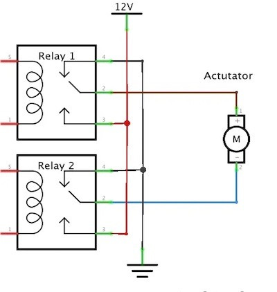
A simple way to reverse polarity is by using a pair of SPDT relays in an H-bridge configuration, as illustrated in the diagram below. The actuator motor will spin in one direction or the opposite, depending on which relay is activated.
Setting it up
For prototyping, I chose to use a smaller actuator, the Progressive Automations PA-MC1, which allowed me to use the double PCA9536 SPDT relay mini module from National Control Devices. This module is sitting on I²C address 0x41.
Let’s start by creating a configuration file for piotserver with an entry for the PCA9536.
{
    "devices": [
        {
            "device_type": "PCA9536",
            "address": "0x41",
            "title": "ACUATOR RELAYS",
            "pins": [
                {
                    "bit": 0,
                    "data_type": "BOOL",
                    "key": "RELAY_1",
                    "gpio.mode": "output"
                },
                {
                    "bit": 1,
                    "data_type": "BOOL",
                    "key": "RELAY_2",
                    "gpio.mode": "output"
                }
            ]
        }
    ]
}
This defines the two variables, RELAY_1 and RELAY_2, for bit positions 0 and 1 of the PCA9536. Next, we connect the relays to the actuator using the H-Bridge circuit, as illustrated in Fig. 1 above.
To extend the actuator, we must set RELAY_1 to true and RELAY_2 to false. To retract it, we set RELAY_1 to false and RELAY_2 to true. Using the REST API, this would look something like:
PUT /values HTTP/1.1
Content-Type: application/json; charset=utf-8
Host: royal9:8081
Connection: close
Content-Length: 32

{"RELAY_1":true,"RELAY_2":false}
This seems a bit clunky and prone to error. We can do better.
Actuator_Device
Since I plan to use the actuator concept often enough, it makes sense to create a specialized device built on top of the existing drivers. Enter the Actuator_Device.
When we set the actuator to true, it extends, then shuts off. When we set it to false, it retracts, then shuts off. The device is a software state machine that controls the two relays and has the following possible states.
Extending - Relay_1 is on, and in the process of extending.
Extended - Extension is complete, and both relays are off
Retracting - Relay_2 is on and in the process of retracting.
Retracted. - Retract is complete, and both relays are off
Unknown/Off - possible error states, or pre-initialization
To use this, we add a “device_type” of ACTUATOR to the “devices” section of our piotserver configuration file.
{
  "devices": [
    {
 ...
    },
    {
      "device_type": "ACTUATOR",
      "pins": [
        {
          "data_type": "ACTUATOR",
          "key": "DOOR_1_STATE",
          "read_only": true
        },
        {
          "data_type": "BOOL",
          "key": "DOOR_1",
          "read_only": false,
          "tracking": "ignore"
        }
      ],
      "description": "PA_MC1 Door Actuator",
      "title": "Actuator 1",
      "params": {
        "extend": "RELAY_1",
        "retract": "RELAY_2",
        "duration": 3
      }
    }
  ]
}
In this example, we specify that the extend function uses RELAY_1 and the retract function uses RELAY_2. We also created a boolean variable called DOOR_1, which can be set from the REST interface, and another variable named DOOR_1_STATE, which can be queried from the REST interface to check the status of the actuator.
We also added an optional duration field that instructs the Actuator_Device to turn the relays off after 3 seconds.
Addendum: The Actuator_Device is an open-loop control. It has no feedback on the actuator's position, but for most applications, running the relay for the duration is sufficient. You may need to experiment with the actual time it takes you to complete an operation under load, but the actuator's specification sheet typically contains information on the operation's completion time.
Extending
To extend the actuator, we run the following HTTP PUT request.
PUT /values HTTP/1.1
Content-Type: application/json; charset=utf-8
Host: royal9:8081
Connection: close
Content-Length: 15
{"DOOR_1":true}
We can check the status of the actuator by immediately issuing the following GET REST query to our piotserver.
http://royal9:8081/values{
"success": true,
"values": {
"DOOR_1_STATE": {
"display": "Extending",
"time": 1749071901,
"title": "Actuator 1",
"value": "2"
},
"RELAY_1": {
"display": "true",
"time": 1749072001,
"title": "Actuator Relays",
"value": "1"
},
"RELAY_2": {
"display": "false",
"time": 1749072001,
"title": "Actuator Relays",
"value": "0"
}
}
}And after the three seconds we specified in the duration field of the config file expired, we will observe that RELAY_1 will shut off.
Retracting
Conversely, to retract the actuator, we issue the following HTTP PUT request.
PUT /values HTTP/1.1
Content-Type: application/json; charset=utf-8
Host: royal9:8081
Connection: close
Content-Length: 16
{"DOOR_1":false}
Now, if we wait a few seconds and issue the following GET REST query to our piotserver, it will show the device has indeed rectracted.
http://royal9:8081/values{
"success": true,
"values": {
"DOOR_1_STATE": {
"display": "Retracted",
"time": 1749072061,
"title": "Actuator 1",
"value": "5"
},
"RELAY_1": {
"display": "false",
"time": 1749072071,
"title": "Actuator Relays",
"value": "0"
},
"RELAY_2": {
"display": "false",
"time": 1749072071,
"title": "Actuator Relays",
"value": "0"
}
}
}If you look carefully at the video below, you can see the LEDs for Relay 1 and 2 turn on and off as the actuator moves.
What else can you do with it?
In the case of the chicken coop, the door slide was thick enough to deter most predators. However, what if I wanted something more substantial? While watching one of our garage door openers, it occurred to me that I could use a similar system to an automatic garage door lock solenoid.
After conducting some research, I discovered that people were repairing the solenoids using inexpensive Universal Car Power Door Lock Actuators they found online.
Unlike the automatic sprinkler valves I use in my irrigation system, these solenoids are directional. That is, the direction of the current flow controls the direction they move. You can wire them the same way as the actuators, just be careful not to apply current for too long, or you will overheat the solenoid.
Automat Piotserverkova
Up to this point, I’ve explained how to activate these devices using REST requests, but they become truly useful when the process happens automatically. Next, we will discuss how to control devices using a “sequence”.
This post is part of the Off-Grid Farm Automation with Raspberry Pi series — a full DIY walkthrough of building a self-hosted system for sensors, valves, and automation, no cloud required.