
Raspberry Pi Internet of Things - part 8
Getting the data and controlling the devices from the REST API

In the introductory post of this Pi Internet of Things (PioT) series, I mentioned that I developed the piotserver app on the Raspberry Pi platform. piotserver is the code that queries the sensors and controls pumps and valves through a REST API.
In this chapter, I will discuss how to configure piotserver to recognize the hardware and devices connected to your Raspberry Pi.
Setting up devices in the config file
One of the first things that piotserver does on start-up is to read its configuration file and set things up accordingly. The configuration file is encoded in JSON, and the default name is “piotserver.props.json”. Its location and name can also be specified with its command line arguments.
(And no, I purposely didn’t use YAML. And yes, all configuration file formats are prone to error.)
The config file supports the following JSON keys:
config
devices
values
sequences
sequence.groups
For now, let’s focus on “devices,” and we will address the other keys in later articles.
Currently, piotserver supports interfacing devices in three ways: the Dallas 1-Wire® protocol, I²C, and using the built-in GPIO pins. I experimented with writing code to explore ways to auto-configure the devices. However, I soon realized that not only was this a non-trivial task, but it was also unreliable.
For example, let’s use the i2cdetect utility to probe the I²C bus and create a list of slave device addresses on my garden setup. This is what the output looks like:
$ sudo i2cdetect -y 1

    0  1  2  3  4  5  6  7  8  9  a  b  c  d  e  f
00:                         -- -- -- -- -- -- -- --
10: -- -- -- -- -- -- -- -- 18 -- -- -- -- -- -- --
20: 20 -- -- -- -- -- -- -- -- -- -- -- -- -- -- --
30: -- -- -- -- -- -- -- -- -- -- -- -- -- -- -- --
40: 40 -- -- -- 44 -- -- -- 48 -- -- -- -- -- -- --
50: -- -- -- -- -- -- -- -- -- -- -- -- -- -- -- --
60: -- -- -- -- -- -- -- -- -- -- -- -- -- -- -- --
70: -- -- -- -- -- -- -- --
What I actually have hooked up consists of the following devices.
0x18 - DS2482-100 is an I²C to 1-Wire bridge
0x20 - NCD MCP23008 Relay+I/O
0x44 - SHT30
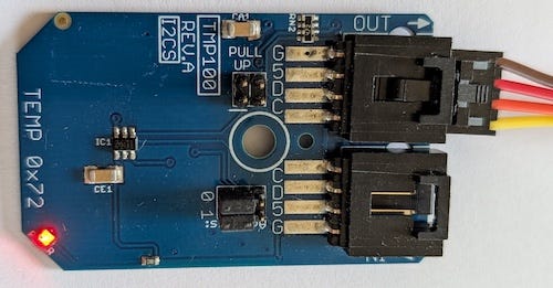
0x48 - TMP100 Temperature sensor
While it’s true that NXP still manages address allocation for I²C devices to prevent address collisions, this list is not publicly available, and some devices can have a user-configurable address. Although there are some unofficial lists on the Internet, there is considerable overlap in most of the address entries, and thus, this method is largely worthless.
Further, while the official I²C specification (UM10204.pdf) mentions (3.1.17) optional support of a Device ID, I have not been successful in getting any device to respond to it.
So for the time being, it’s probably better that we configure the devices manually. So let’s start with a simple example.
Setting up a Temperature Sensor
Let’s assume we have a TMP100 temperature sensor on our Raspberry Pi I²C bus wired for slave address 0x48. We can verify this using the i2cdetect command as shown above.
Our config file would look something like:
{
    "devices": [
        {
            "address": "0x48",
            "data_type": "TEMPERATURE",
            "device_type": "TMP10X",
            "key": "TEMP_48",
            "title": "Temperature Sensor 48",
            "interval": 30
        }
    ]
}
Where the JSON keys are defined as:
address - I²C slave address.
data_type - TEMPERATURE indicates that the data value is in degrees Celsius
device_type - The device plug-in name for this device.
key - The name of the JSON key we will use to query this device value later
title - Text description of the device, for the user interface
interval - how often should the plug-in query the device for its value
Once the piotserver has completed its start-up process, it will then query the TMP10X device on address 0x48 every 30 seconds and store its value under the variable TEMP_48.
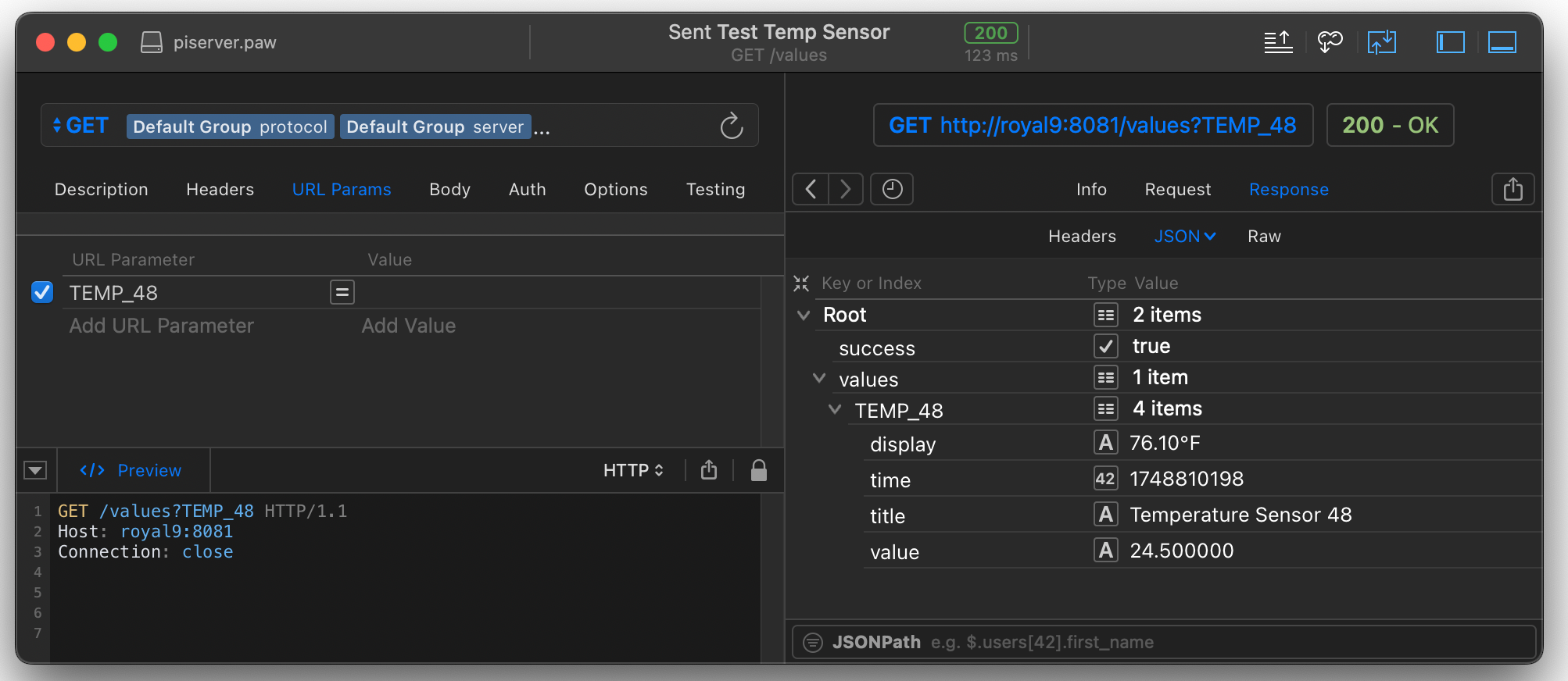
We can then issue a GET REST query to our piotserver. The server is configured with a local DNS entry of royal9 and uses port 8081. To query a variable, we use a path of values and the argument TEMP_48
http://royal9:8081/values/?TEMP_48 And I received the following reply, showing that the sensor read 76.10°F. at UNIX time stamp of 1748810448, which was Sun Jun 01 2025 15:40:48 GMT-0500 (Central Daylight Time)
{
  "success": true,
  "values": {
    "TEMP_48": {
      "display": "76.10°F",
      "time": 1748810448,
      "title": "Temperature Sensor 48",
      "value": "24.500000"
    }
  }
}
By the way, this is probably a good time to revisit my article on Debugging REST API using PAW. Since I wrote it, the company that developed the tool was acquired by Nokia and renamed the product RapidAPI.
I will demonstrate how to do some cool things with that variable, TEMP_48, in a later article. However, for now, let’s try another slightly more complex example.
Setting up a Relay and a Rain Sensor
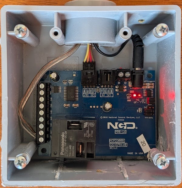
I also have an MCP23008 from National Control Devices interfaced on the I²C bus at device address 0x20. The MCP23008 is configured with a 30 A relay and seven additional GPIO ports. The relay is hooked up to our greenhouse light, and one of the GPIO ports is connected to an Orbit Rain sensor.
I have added the following JSON to the device entry of the config file.
{
    "device_type": "MCP23008",
    "address": "0x20",
    "title": "NCD Relay+I/O",
    "pins": [
        {
            "bit": 0,
            "data_type": "BOOL",
            "key": "GREENHOUSE_LIGHT",
            "title": "Greenhouse Light",
            "gpio.mode": "output"
        },
        {
            "bit": 7,
            "data_type": "BOOL",
            "key": "RAIN_SENSOR",
            "title": "Orbit Rain Sensor",
            "gpio.mode": "input"
        }
    ]
}
This tells the piotserver that I have an MCP23008 on I²C address 0x20. I didn’t specify a query interval, since the rain sensor is relatively slow to change, and I can use the default delay of the MCP23008 plug-in (60 seconds).
I have also specified that bit 0 of the device is used for output, and its variable name is GREENHOUSE_LIGHT. I am also assigning bit 7 as an input, with the variable name RAIN_SENSOR.
To test this, I will issue a GET REST query to our piotserver ( testserver port 8081)
http://royal9:8081/values/?GREENHOUSE_LIGHT&RAIN_SENSOR{
"success": true,
"values": {
"GREENHOUSE_LIGHT": {
"display": "true",
"time": 1748812949,
"title": "Greenhouse Light",
"value": "1"
},
"RAIN_SENSOR": {
"display": "false",
"time": 1748812949,
"title": "Orbit Rain Sensor",
"value": "0",
"tracking": "track.changes"
}
}
}
GREENHOUSE_LIGHT & RAIN_SENSORThis indicates that our Greenhouse light is on and that the rain sensor is dry.
Setting Values
To toggle the Greenhouse light, we use a REST PUT command and specify the variable we want to set in the request body.
PUT /values HTTP/1.1
Content-Type: application/json; charset=utf-8
Host: royal9:8081
Connection: close
Content-Length: 25

{"GREENHOUSE_LIGHT":true}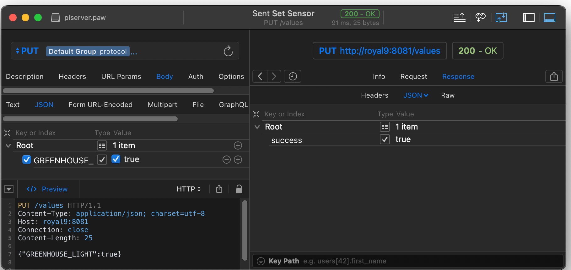
Using 1-Wire Sensors
We can also specify sensors that use the Dallas 1-Wire® protocol in the config file. These sensors are mapped to the file system on the Raspberry Pi. The file path depends on whether you have the sensor directly hooked up to the Raspberry Pi GPIO lines or if you are interfacing through a DS2482-100 chip. I wrote a lot of details about this in my article on the 1-Wire sensors.
In this example, I have a DS2482 temperature sensor that I buried a few inches below the soil of our garden. The sensor is interfaced to a DS2482-100 using the OWFS service. The sensor shows up at the filepath /mnt/1wire/28.793434000000/
We can test this from the command shell.
$ ls -l  /mnt/1wire/28.793434000000
total 0
-r--r--r-- 1 root root   16 Jun  1 16:33 address
-rw-rw-rw- 1 root root  256 Jun  1 16:33 alias
-r--r--r-- 1 root root    2 Jun  1 16:33 crc8
drwxrwxrwx 1 root root 4096 Jun  1 17:01 errata
-r--r--r-- 1 root root    2 Jun  1 16:33 family
-r--r--r-- 1 root root   12 Jun  1 16:33 fasttemp
-r--r--r-- 1 root root   12 Jun  1 16:33 id
-r--r--r-- 1 root root   12 Jun  1 17:01 latesttemp
-r--r--r-- 1 root root   16 Jun  1 16:33 locator
-r--r--r-- 1 root root    1 Jun  1 17:01 power
-r--r--r-- 1 root root   16 Jun  1 16:33 r_address
-r--r--r-- 1 root root   12 Jun  1 16:33 r_id
-r--r--r-- 1 root root   16 Jun  1 16:33 r_locator
-r--r--r-- 1 root root    9 Jun  1 17:01 scratchpad
-r--r--r-- 1 root root   12 Jun  1 16:33 temperature
-r--r--r-- 1 root root   12 Jun  1 16:33 temperature10
-r--r--r-- 1 root root   12 Jun  1 16:33 temperature11
-r--r--r-- 1 root root   12 Jun  1 16:33 temperature12
-r--r--r-- 1 root root   12 Jun  1 16:33 temperature9
-rw-rw-rw- 1 root root   12 Jun  1 17:01 temphigh
-rw-rw-rw- 1 root root   12 Jun  1 17:01 templow
-rw-rw-rw- 1 root root   12 Jun  1 17:01 tempres
-r--r--r-- 1 root root   32 Jun  1 16:33 type

$ cat /mnt/1wire/28.793434000000/temperature
23.8125
Given this scenario, we add the following JSON to the device entry of the config file.
{
  "address": "/mnt/1wire/28.793434000000/",
  "data_type": "TEMPERATURE",
  "device_type": "1wire",
  "key": "PLOT1",
  "title": "Soil Temp Plot 1",
  "interval": 3600
}
Similar to the previous entries, we have also specified that the readings be taken every 3600 seconds (i.e., every hour). We query in the same way as we would the other variables.
http://royal9:8081/values/?PLOT1 {
"success": true,
"values": {
"PLOT1": {
"display": "75.09°F",
"time": 1748815799,
"title": "Soil Temp Plot 1",
"value": "23.937500"
}
}
}Using GPIO Pins
GPIO devices are specified similarly. We use a device_type of GPIO, but we need to provide a bit more information about how the ports are configured. For this example, I have the Raspberry Pi connected to a Waveshare 8-Channel Relay Expansion Board. The board utilizes GPIO pins 5, 6, 13, 16, 19, 20, 21, and 26. In the config file, I use the term BCM instead of pins because it refers to the Broadcom chip on the Pi.
In this example, I have defined each of the pins as outputs and assigned the keys RELAY_1 to RELAY_8.
 {
  "device_type": "GPIO",
  "title": "RPi Relay Board",
  "pins": [
    {
      "BCM": 5,
      "data_type": "BOOL",
      "gpio.mode": "output",
      "key": "RELAY_1",
      "title": "relay 1"
    },
    {
      "BCM": 6,
      "data_type": "BOOL",
      "gpio.mode": "output",
      "key": "RELAY_2",
      "title": "relay 2"
    },
    {
      "BCM": 13,
      "data_type": "BOOL",
      "gpio.mode": "output",
      "key": "RELAY_3",
      "title": "relay 3"
    },
    {
      "BCM": 16,
      "data_type": "BOOL",
      "gpio.mode": "output",
      "key": "RELAY_4",
      "title": "relay 4"
    },
    {
      "BCM": 19,
      "data_type": "BOOL",
      "gpio.mode": "output",
      "key": "RELAY_5",
      "title": "relay 5"
    },
    {
      "BCM": 20,
      "data_type": "BOOL",
      "gpio.mode": "output",
      "key": "RELAY_6",
      "title": "relay 6"
    },
    {
      "BCM": 21,
      "data_type": "BOOL",
      "gpio.mode": "output",
      "key": "RELAY_7",
      "title": "relay 7"
    },
    {
      "BCM": 26,
      "data_type": "BOOL",
      "gpio.mode": "output",
      "key": "RELAY_8",
      "title": "relay 8"
    }
  ]
}
For example, to set relays 1 and 4, we do a PUT operation, specifying both relays in the body of the PUT.
PUT /values HTTP/1.1
Content-Type: application/json; charset=utf-8
Host: royal9:8081
Connection: close
Content-Length: 31

{"RELAY_1":true,"RELAY_4":true}
It’s about time
Now that we have mapped the devices to value names, we can expand on this concept. In my upcoming posts, I will discuss how to trigger a series of events that will set these values, how to record changes in those values in the built-in database, and how to create pseudo-devices that build upon the actual devices. I will also cover how to protect your devices from being hacked and accessed by unauthorized users.

This post is part of the Off-Grid Farm Automation with Raspberry Pi series — a full DIY walkthrough of building a self-hosted system for sensors, valves, and automation, no cloud required.