
Raspberry Pi Internet of Things - part 17
PWM, a better way to control sprinkler valves

In an earlier article on managing irrigation valves, I shared that the solenoids used in common sprinkler valves like the Hunter PGV or Rain Bird CPF100 are usually powered by a 24VAC system. This voltage probably stems from early 20th-century HVAC controls. But I have a few reasons for avoiding using AC. In our agricultural environment, I want the option of being entirely solar-powered and/or employing a battery backup for power outages. Using DC also removes me from the damage that power spikes from the utility were doing to my cheap AC power supplies.
Since most solenoids are unaffected by polarity, they can be theoretically driven with DC. While I suspect that just using DC has the potential to overheat the coils, once a solenoid is energized, it needs significantly less power to maintain it engaged.
Ray Wang at OpenSprinker researched this and found he could reliably drive these kinds of solenoids with an initial higher impulse voltage, and then lower the voltage to reduce the power consumption. This is how the voltage booster for the OpenSprinkler, OSPi, and OpenSprinkler Bee systems works.
In my second evolution of the sprinkler system, I prototyped a booster circuit based on relays and a lower-voltage DC/DC buck regulator. But the relays and charge pumps are just a proof of concept for me. There is a better way.
Pulse Width Modulation (PWM)
I have built a few systems in the past that use Pulse Width Modulation (PWM) to regulate the average power supplied to devices. Mostly they were for LEDs and automotive lamps, but I think PWM will work for the sprinklers too.
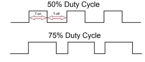
PWM works by quickly switching signals between an on and off state, and by varying the ratio of on to off time. The duty cycle (power-on percentage) sets the average power. For example, a 75% duty cycle provides 3/4 of the max power. By changing the pulse width at a high enough frequency, you can precisely control the amount of power delivered.
The concept of Pulse Width Modulation (PWM) dates back to the 1930s with vacuum tube-based circuits. Later, in the 1970s and 1980s, with the introduction of specialized integrated circuits and MOSFET devices, PWM became more practical for use with motors and solenoids. These days, PWM is the go-to way to control the brightness of lamps and LEDs.
The invention of the first PWM chip, the SG1524, is another one of those success stories that spawned an entire industry.
The DRV103
Today, the DRV103 PWM control from Burr Brown/Texas Instruments is one of the most popular PWM chips. While the DRV103 was originally designed for reliable control of inductive and resistive loads in automotive applications such as anti-lock brake systems, it can also drive electromechanical devices like solenoids, coils, valves, and heaters.

The DRV103 is also an excellent fit for my sprinkler valve application:
It efficiently operates within the voltage (8 - 32VDC) and current ( 1.5 and 3A) range of sprinkler solenoids.
The input signal turns on at +2.2V and +5.5V; thus, it is compatible with Raspberry Pi GPIO levels.
It has built-in thermal and current limit shutdown. (short circuit detection)
It also has a signal that indicates when a short circuit or overheating occurs.
You could even use the DRV103 to control the brightness of lamps and LEDs, but are chips better suited for that task, such as the LM3404 or the MAX7316.
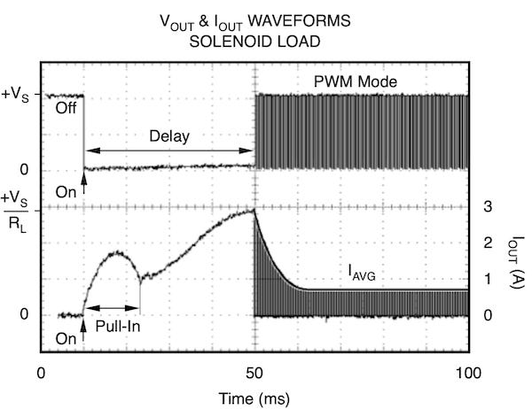
This chip stands out because it can be configured to begin with a constant DC output (100% duty cycle), providing the solenoid a strong initial pull-in, and then automatically transition to a PWM soft hold mode.
Calculating the Parameters
Let’s make the following assumptions about the environment I plan to build for.
I am using sprinkler values like the Hunter PGV or Rain Bird CPF100.
Each valve will have its own dedicated DRV103 circuit. There is enough water pressure that multiple valves will often be open at the same time.
The distance from DRV103 to the furthest valve is approximately 125’ using standard direct burial 18 AGW sprinkler wire bundle.
This gives us a wire resistance of approximately 1.6 Ω (125 ft × 2 × 6.39 Ω/1000 ft).
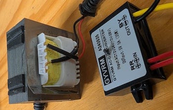
I am powering the system with an uninterruptible DC power supply where the voltage can range from 14.1VDC (when plugged in) to 11.82VDC (low battery).
— Let’s say 13.5VDC as a good middle ground.
I did some research using various sources, including the manufacturer’s datasheets, Ray’s observations, some community-measured data(aka, knuckleheads on the internet), and even some fooling with ChatGPT. I came up with the following generalizations about valve solenoids.
Coil Resistance: 32–34 Ω (typical range)
Wire Resistance: 1.6 Ω (round-trip for ~125 ft of 18 AWG)
Total Resistance Range: 33.6 Ω to 35.6 Ω
Activation Voltage: 13.5V
Activation Current: 13.5 V / 33.6 Ω ≈ 0.4018 A ≈ 402 mA
Activation Time: 30 to 150 ms
Holding Current: ≈ 250mA
Holding Voltage: 250mA × 33.6 Ω = 8.40 V
I want to use PWM to apply enough average current to keep the plunger pulled in, but not so much that it overheats. Thus, if we're going to simulate the 8.4 V holding voltage (Vavg) from a 13.5 VDC source using PWM, we would do the following to calculate the required duty cycle (D):

If we look at this from the point of view of power. At full power 402mA:


For holding power of 250mA:

Which gives us a power savings of:

To review: After powering the solenoid with 13.5 VDC for at least 150 ms, we can maintain the plunger position just using a 62.2% duty cycle pulse. Not only does this extend the lifecycle of the plunger by not overheating it, but it also saves us quite a bit of battery power.
Programming the DRV103
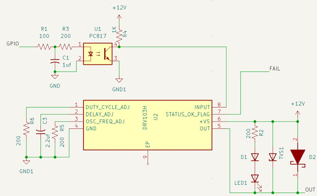
According to the DRV103 datasheet, it can operate from an 8V to 32V power supply with excellent performance. It’s good practice to add a bypass capacitor from +Vs (pin 6) to GND (pin 4), to manage the spikes from switching.
A 1µF tantalum bypass capacitor is adequate for uniform duty cycle control when switching loads of less than 0.5 amps. Larger bypass capacitors are required when switching high current loads. A 22µF tantalum capacitor is recommended for heavy-duty (3A) applications.
Activation Time
We define the time from when we apply a constant DC to the solenoids to when it switches to PWM as the activation time. This delay can be set by a capacitor (CD) connected from the delay adjustment (pin 2) of the DRV103 to GND.
For our valves, this is 30 to 150 ms or 0.15 seconds.

But on second thought, let’s design for 0.5 seconds (500 ms) of full-power activation. This gives us some wiggle room for reliable valve opening, especially for high-pressure (>100 PSI) or slower valves (e.g., older units).

The closest industry standard value will be a 470 µF capacitor.

PWM Frequency
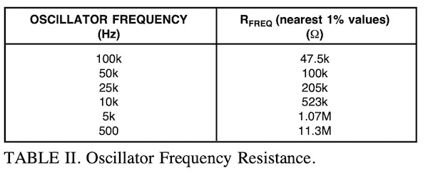
We also need to set the oscillation frequency for the PWM. This is programmed by connecting a resistor (RFREQ) between the Osc Freq Adj pin (pin 3) and ground. From the datasheet, the formula for this value is:

I spent some time researching this, hashing through the math, and fighting with the so-called modern AI tools (don’t depend on them; they make a lot of mistakes).
Most of the documentation on this topic relates to proportional solenoids. These are not the same as sprinkler valves. Proportional valves are designed to be variable, whereas a sprinkler valve is binary. They are either on or off.
Finding the proper frequency was not easy, and I might still be wrong, but here is what I know.
I concluded that 25 kHz is most likely a good choice for the PWM oscillation frequency of our sprinkler valve solenoids:
Above audible range: Prevents annoying coil whine (human hearing tops out around 20 kHz).
Efficient: Low enough that switching losses are minimal and compatible with typical solenoids.
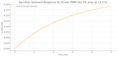
At 25kHz, the current ramp increases smoothly and stabilizes around 0.24 A, which matches our holding current. Since the solenoid coils’ inductance filters out the ripple, we get near-DC behavior. There’s no abrupt switching in current because of the inductive time constant.

Which is much longer than the 40 μs PWM cycle.
Using Table II above, we only need to hook up a 205kΩ to the Osc Freq Adj pin (pin 3) and ground to get 25hKz.
Duty Cycle
Duty cycle is easily programmed by connecting a resistor between the Duty Cycle Adjust pin (pin 1) and ground. According to the datasheet, the formula is:

So for a 62.2% duty cycle:

The closest standard resistor value is 160 kΩ, which gets us 65.6%.
Meh, 65.6% is close enough to 62%
- Mediocrates
RFI/ EMI and all that good stuff
If we look at the system from the point of view of a Radio Engineer or HAM, we have a bunch of antennas in the yard transmitting at 25Khz. The good news is:
25 kHz is not a regulated RF band — it’s far below anything like AM/FM, aviation, or ISM (industrial/scientific/medical) bands.
Most things around 25 kHz are ultrasonic, wired, or low-power and localized.
The long 18 AWG wires won’t radiate significantly at 25 kHz — they act more like low-pass filters due to wire impedance and load inductance.
These wires are low to the ground - Wires in the ground (or close to it) are capacitive-coupled to earth, and drain high-frequency noise, reducing the antenna effect dramatically. The Earth is a giant RF sink.

To get a little more geeky: 25 kHz is a long wavelength (~12 km).

Even at 125 feet (≈38 m), the underground wire is less than 0.003λ, making it a very poor antenna.
At best, we could add a 10 to 22 Ω, 1/4W non-inductive resistor (carbon film or metal film) in series with the DRV103 output, but I doubt it’s worth it.
How You Get So Fly!
These garden solenoids act as electrical inductors — they store energy in a magnetic field when current flows through them. When you suddenly turn off the current, the inductor doesn’t want to stop — it tries to keep the current flowing.
This causes a voltage spike (sometimes hundreds of volts) across the inductor. This inductive kickback is often called flyback. It can damage the DRV103 by overvoltage and EMI, leak back to other circuits nearby, like the Raspberry Pi, and blow them out.
We can alleviate much of this by adding a Schottky Rectifier and a Transient Voltage Suppression (TVS) diode across the output. The Schottky is a fast-switching diode and gives the current a path to go when it comes back in reverse, and the TVS will clamp any surge above ~18 V.
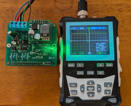
The prototype
I built a quick and dirty ( is there any other kind 😎 ) Raspberry Pi add-on board to test my proof of concept. I hooked up two DRV103s, one to GPIO5 and the other to GPIO6. I also added a Polulu D36V50F5 step-down voltage regulator, which allowed me to use a single 12V battery to test the project.
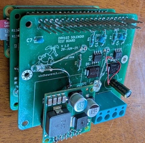
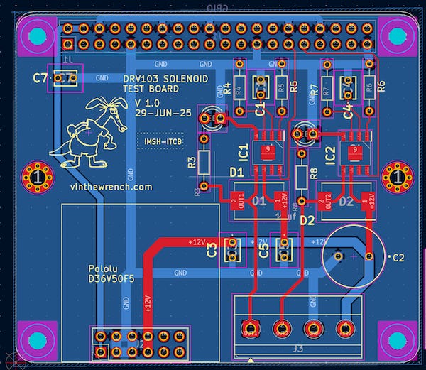
I learned a few more things after my first attempt using KiCad to build a Raspberry Pi add-on card, and once again sent it off to EasyPCB and had a prototype in a few days. Made a few mistakes, did some field repairs, and … it worked.
I was able to toggle the GPIO from the command line using the gpiod library, which caused the valve to open and close.
# install the library
sudo apt-get install gpiod libgpiod-dev

#set GPIO5 as an output
pinctrl set 5 op

#turn GPIO5 on and off
pinctrl  set 5 dh
pinctrl  set 5 dl
This was just a test.
This project was just a proof of concept. Since then, I have made some improvements and am prototyping another sprinkler controller card. I’ll save those details for later. The updated circuit uses optoisolators to further protect the Raspberry Pi from EMI issues.
This post is part of the Off-Grid Farm Automation with Raspberry Pi series — a full DIY walkthrough of building a self-hosted system for sensors, valves, and automation, no cloud required.