
Raspberry Pi Internet of Things - part 14
Rolling my own I²C and 1-Wire interface card

Earlier in this series, I wrote about how I used the I²C and Dallas 1-Wire protocol to communicate with the various sensors attached to my Raspberry Pi. In the process of building and deploying my prototype, I became concerned with protecting the Raspberry Pi board from electrostatic discharge (ESD). I experimented with various interface cards from NCD, SparkFun, and AB Electronics.
I especially appreciated how NCD utilized a TI ISO1541 to shield the SCL and SDA I²C signals, as well as an isolated DC/DC power supply. This was one of the best ways to prevent spikes on the I²C power from propagating back to the Pi.
Another problem on my list was that some of the I²C devices I needed to communicate with were situated farther away than the specification’s recommended distance. I was able to overcome this limitation in a previous project by utilizing a mini module from Sparkfun that utilized the PCA9615 to convert I²C signals to differential signals. I also tried the 1-Wire Pi Plus board from AB Electronics in the UK to protect the Pi from electrostatic discharge (ESD).
All these devices worked as a proof of concept, but assembling them was somewhat of a hack. I needed something better since I planned to reproduce this arrangement several times on the farm.
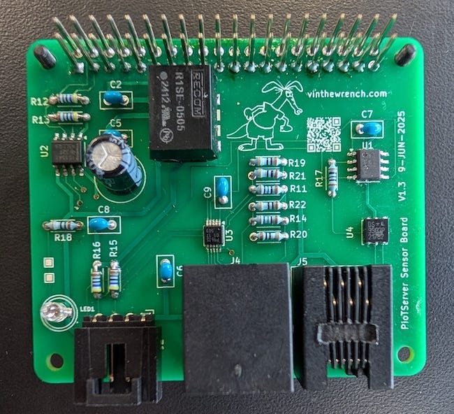
So I dug deep into the product data sheets and articles from Texas Instruments, NXP Semiconductors, and RECOM Power. I spent some time analyzing the manufacturers’ reference designs; you can learn a great deal about how they intended the chips to be used. Using them, I was able to design my own Raspberry Pi add-on board, which combined the I²C and 1-Wire functions with proper ESD isolation.
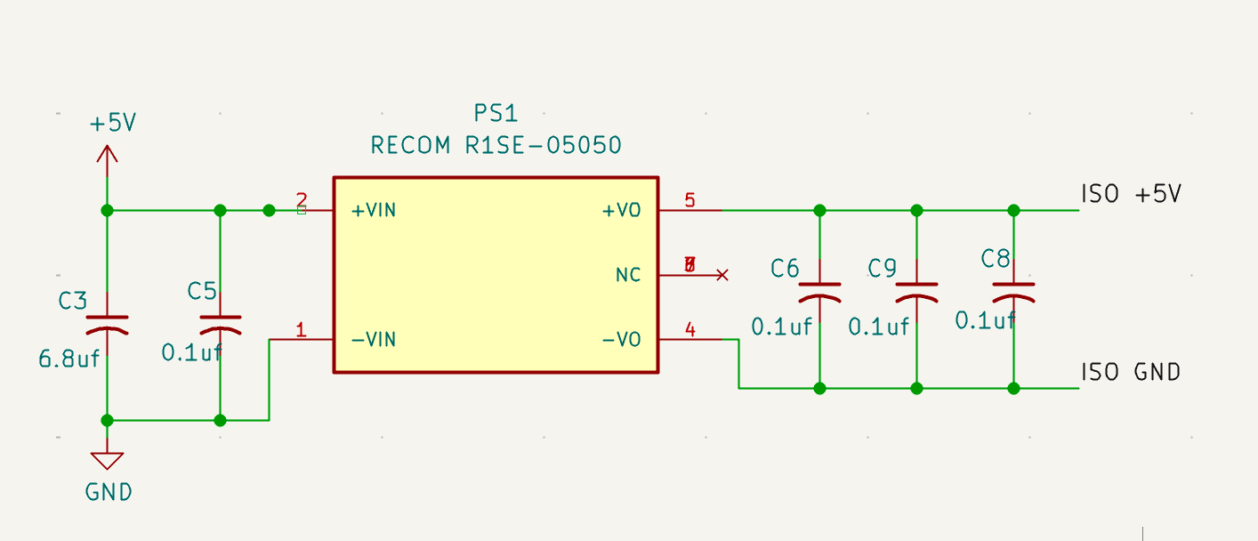
Power supply isolation
The first thing I wanted to do was to protect the power that feeds the Raspberry Pi from any spikes or even shorts that might occur on the I²C and 1-Wire cables. I selected the R1SE-05050 DC/DC converters from RECOM Power. The R1SE-05050 takes the Raspberry Pi’s +5V and produces 5V with approximately 1 kV of isolation. This device costs approximately $3.50 at Mouser (all prices are for a quantity of 25).
I highly recommend that anyone involved in circuit design download their books on power supply design and EMC.
I²C Isolation
I used the ISO1541 to isolate and protect the Raspberry Pi’s I²C SCL/SDA signals. Texas Instruments provides a wealth of information on protecting I²C on their website. The chip also allowed me to level-shift the SCL/SDA signals from 3.3V to a more robust 5V, and also make them compatible with NCD’s nodeLynk devices.
One thing to keep in mind is that there are two versions of this product available: ISO1540 and ISO1541. They are slightly different. The ISO1540 has two isolated bidirectional channels for SCL and SDA, while the ISO1541 has one bidirectional data channel for SDA and a unidirectional clock channel for SCL. What this means is that if you use the ISO1541, you must be careful to route the correct signals to the chip when laying out your board. (Ask me how I know!)
The ISO1541DR costs about $2.61 from Mouser, and the Molex socket, compatible with NCD’s nodeLynk 70553-0003, costs about $0.95
I²C Differential Driver
I wanted to add the capability to communicate I²C over longer distances. (For details, please see the section on extending I²C distance in part 4 of this series.) For this, I used the NXP PCA9615DP Differential I²C-Bus Buffer. The chip cost was approximately $2.60, excluding the costs of a few resistors and an RJ45 connector.

I powered the PCA9615 from the isolated 5V power supply. I also chose a 390/100/390 Ω bias resistor network so that it would be compatible with a SparkFun QwiicBus EndPoint on the receiving side. ( For more information on the resistor choice, see the PCA9615 datasheet section 7.2. on dI2C-bus side differential pair)
If you plan to connect it to a SparkFun device, remember that QwiicBus devices operate at 3.3V, not 5V.
Rather than using the QwiicBus connectors, I soldered a cable with 4-pin Molex SL 70553 2.54mm connectors that could be directly connected to a nodeLynk device.
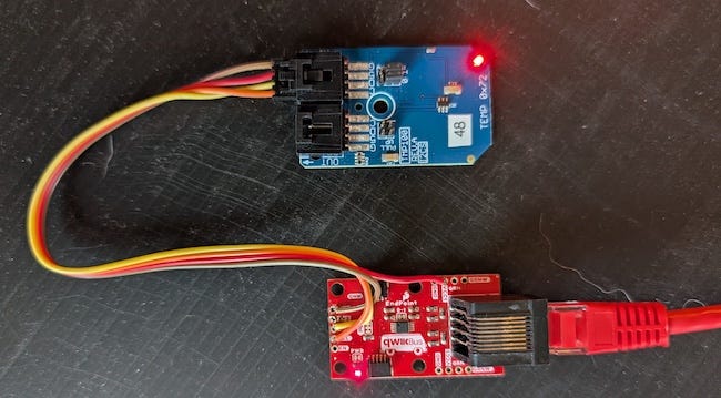
Note that the nodeLynk cables are configured to go from the OUT→ of one nodeLync device to the →IN of the next device. It took me a minute to realize that I could connect the cables backwards. You will know that you are doing it wrong if the LED on the nodeLynk board is not lit brightly. The proper cable colors configuration is:
RED - 5V
BRN - GND
ORN - SDA
YEL - SCL
Also, if you look at the photo above, you will see that I hooked up the RED wire to the VCC1 pin of the Endpoint. I am still experimenting with this setup. I suspect that I could use some of the STEMMA 4 Pin JST SH devices directly at 5V.
1-Wire Interface
Since I use the DS18B20 temperature sensors in my farm automation, I also need to protect the 1-Wire interface system. In my article about 1-Wire, I discussed why I selected the DS2482S-100+ 1-Wire Master over going directly to the Raspberry Pi GPIO line. Integrating this chip into my design was relatively easy; however, I also added the DS9503P ESD Protection Diode, which gave my circuit approximately 27 kV of isolation.
The DS2482S-100+ cost was about $1.80, and the DS9503P around $1.54.
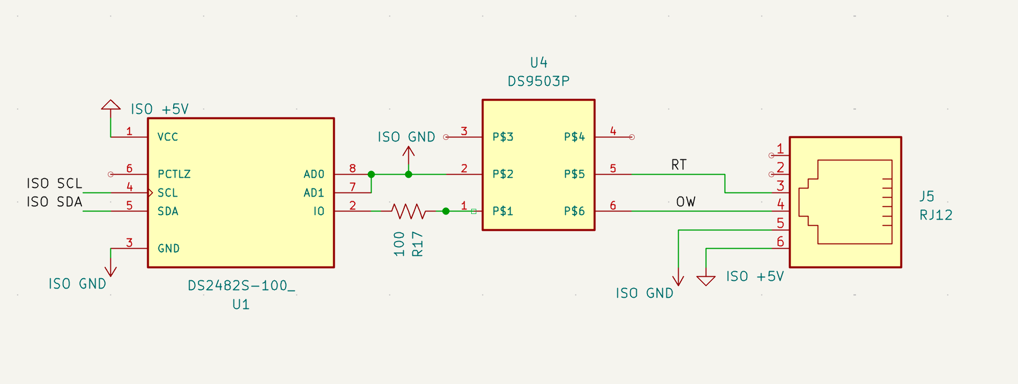
For this design, I used an RJ12 connector; however, anything with 3 or 4 pins would suffice. If you use an RJ12, the 6P6C color code is as follows:
GRN - ISO +5V
ORN - ISO GND
BLU/WHT - OW
BLU -RT
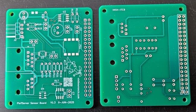
PCB and Schematic Design
I have an on-and-off romance with designing circuits and PC boards, and have used a variety of different CAD systems over the last 50 years. How do I say it, they all suck, some more than others. I suppose the current rage is KiCad (maybe pronounced "kee KAD"). "That's all I have to say about that."
I posted the schematic and KiCad-compatible sources for making your board on my GitHub site.
While several companies will take the Gerber files generated from KiCad and send you back a bare printed circuit board, I wanted one that not only has a good reputation but also operates in the USA, preferably as a small business. I found that Sunstone Circuits, based in Oregon, was running the online site easypcbusa.com.
EasyPCB was able to take the design file produced by KiCad and deliver a high-quality board for me for approximately $10 per board with a 2-day build time. (Sadly, the USPS takes a week to get them from Oregon to Arkansas, but that’s another saga of its own.)
Board Assembly
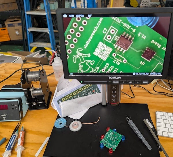
Populating the boards was not exceptionally difficult. I needed to brush up on my SMD soldering skills, but after a few minutes, I got the hang of it. Some of the SMD parts, such as the RECOM DC/DC unit and the DS9503P, were a bit challenging due to the pad layout. For these, I used a cheap hot-air rework station and solder paste, but for most parts, I was able to use a trusty old-school Weller soldering station.
Since I don’t have the eyesight I had in my 20s, one thing I personally found very helpful was a digital microscope. I used to use a magnifying loupe to see any minuscule soldering remnants, but the microscope is so much easier to work with.
There are lots of videos available online that demonstrate how to solder SMD parts. One of my favorite videos is from David L. Jones from EEVblog.
Assembly and Design Verification
The design wasn’t that complicated, but it took me two board revisions to get it correct. I tried to optimize my traces, and I thought I could get away with swapping the SCL/SDA signals going into the ISO1541. (see my note above about the SO1540 vs ISO1541). I was able to identify the problem quickly by tracing the signals using a low-cost digital oscilloscope. I had to cut and rework some of the traces, and once it was working, I updated my design and ran another small batch of boards from EasyPCB.
Another helpful tool was the i2cdetect utility on the Raspberry Pi. The DS18B20 should appear as address 0x18. I also plugged in a few other I²C devices on known addresses, both on the isolated I²C and on the other end of the differential bus.
sudo i2cdetect -y 1
     0  1  2  3  4  5  6  7  8  9  a  b  c  d  e  f
00:                         -- -- -- -- -- -- -- --
10: -- -- -- -- -- -- -- -- 18 -- -- -- -- -- -- --
20: 20 -- -- -- -- -- -- -- -- -- -- -- -- -- -- --
30: -- -- -- -- -- -- -- -- -- -- -- -- -- -- -- --
40: 40 -- -- -- -- -- -- -- -- -- -- -- -- -- -- --
50: -- -- -- -- -- -- -- -- -- -- -- -- -- -- -- --
60: -- -- -- -- -- -- -- -- -- -- -- -- -- -- -- --
70: -- -- -- -- -- -- -- --
It will be fun, they said.
The final design of my own I²C interface card bill of materials came to a cost of approximately $25 to $30, excluding the cost of my engineering and assembly time. But it was a valuable learning experience, and now that I have the skill mastered, I will likely design some additional boards in the future.
This post is part of the Off-Grid Farm Automation with Raspberry Pi series — a full DIY walkthrough of building a self-hosted system for sensors, valves, and automation, no cloud required.
About that 27kV Air Gap Thing…
Someone on Hackaday mentioned that 27kV could arc across 30mm in air and suggested potting the board and spreading out components to handle that kind of voltage. While that sounds legit, it's worth clearing up what that 27kV spec actually means.
That number usually comes from the IEC 61000-4-2 ESD test standard — it's a tightly controlled lab test using low-energy pulses with specific waveforms and a metal discharge tip. It doesn’t mean your board can survive a 27kV lightning zap or a random high-voltage event in the field.
For this I²C interface board, the goal wasn't to make it lightning-proof. The goal was to add real-world protection against typical ESD and EMI nastiness that shows up in noisy environments. So yes, there’s some spacing and filtering, but no, it's not invincible. Potting might help, but layout, grounding, and realistic expectations go a long way too.
I had the wrong Molex connector linked; the correct one for nodeLync is 70553-0003
https://www.mouser.com/ProductDetail/Molex/70553-0003