
Raspberry Pi Internet of Things - part 2
Controlling the Irrigation valves.


This article continues my Pi Internet of Things (PioT) series about farm automation. Let’s build on my earlier article about our irrigation infrastructure.
I want to share more lessons we learned since our first install. After a year, I had another leak we had to dig up and fix. Once again, this reinforces the importance of allowing the solvent to cure before applying pressure.
The other lesson I learned was about proper winter shutdown. Although I had built a drain system for the winter, I had forgotten to leave the above-ground ball valves open. When the water trapped in the ball valves froze, the expansion of ice crystals created enough water pressure that the balls exploded.
I was surprised that it got cold enough to freeze the valve in my creek water tank project. Lessons learned: after draining the system, leave the ball valves open.
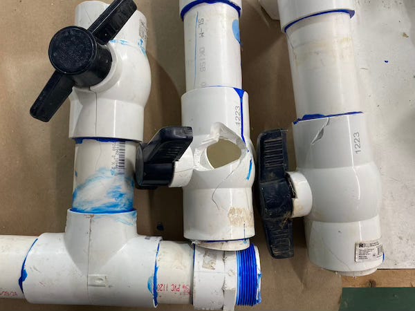
As part of the system repair, our design also evolved to install a pipe union under the shutoff valves in case we ever have to replace them again. I also realized there was no need to continue the 2” pipe above ground; I could transition it to 1” and use a lower-cost valve.
Driving Sprinkler Valves
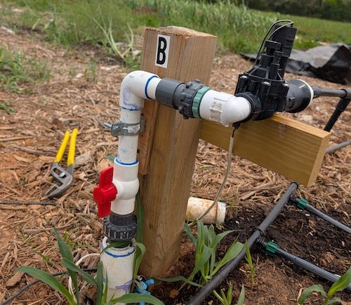
In-line automatic sprinkler valves, such as the Hunter PGV or Rain Bird CPF100, control the water used for our crop irrigation. The genius of the design of these devices is often taken for granted. I encourage you to take a few minutes and watch the video below to see how they work.
As the video above mentions, an electromechanical solenoid controls the valve’s operation. Typically, sprinkler systems use 24- 28VAC. My first attempt at building a system used a 24 VAC transformer. But this ended abruptly after a voltage spike blew a hole in the cheap DC/DC converter I used.
Let me be more direct.
Most solenoids are insensitive to polarity; there is no reason why we can’t operate them with direct current (DC) instead. DC also has the advantage of functioning during power failures using batteries and even solar power.
Kudos to Ray Wang at OpenSprinker for doing some amazing research on this very topic. Ray found that he could reliably drive the solenoid with a higher impulse voltage; once the solenoid is activated, lower the voltage to reduce the power consumption. The OpenSprinkler, OSPi, and OpenSprinkler Bee systems do this with some form of a booster circuit.
The circuit below uses an MC34063 buck switching regulator to charge up a capacitor to 24 V. Once the solenoid is engaged, it bypasses the regulator. It supplies the lower 5V to the valves to keep them open.

Another way to do this is by using an additional relay in place of the booster circuit with two power supply voltages. One is for the boost voltage, and the other is for holding.
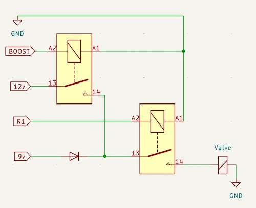
This design would require an additional relay, a DC/DC buck regulator, and a diode. My system already had the extra relay available, so I built a prototype using a Pololu D36V50F7 to give me 7.5 V holding voltage.
To test this out, I ran about 100 feet of 18 AWG wire to a CPF100 and wrote a simple app to toggle some relays. I got great repeatable results.
Reading the voltages at the solenoid, I observed the boost voltage of 13.4 V at 227 mA, and after the voltage drop across the diode, the holding voltage read about 6.8V at 139 mA.
I found that this setup worked reliably. It also had the advantage that I could control the length of the boost voltage using software.
The Relay Interface
One of the primary reasons I prefer controlling the valve solenoids with relays is that they are more resilient to voltage spikes and better isolated than semiconductor circuits.
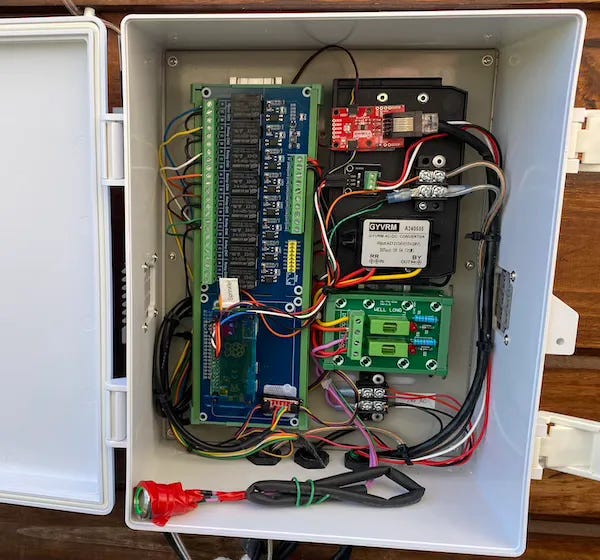
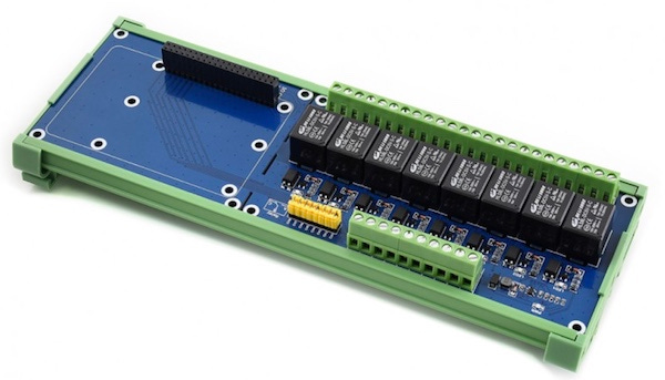
One of the best solutions I found for my application was the Waveshare 8-Ch Relay Expansion Board. The Raspberry Pi (I used a Pi Zero 2 W) fits upside down onto the 40-pin connector. The Waveshare is a well-engineered, quality product. I especially liked that it came with DIN C45 rail hardware, the GPIO interface to the relays had PC817 opto-isolators, and like most of their products, Waveshare also provided a schematic diagram.
It pisses me off that we don’t make these in the USA. It’s not rocket science! Wake up folks.
Another option was to use one of the commonly available SPDT relay boards, like the SainSmart 16-channel module, and interface over I2C with something like this PCA9671 card from Iowa Scaled Engineering. Another great USA company!
I wrote and tested piotserver drivers for the Waveshare and the PCA9671 to handle sprinkler control.
OpenSprinkler Pi (OSPi)
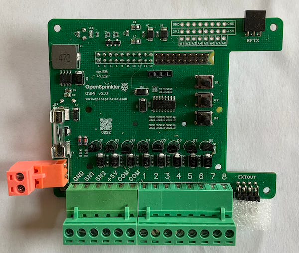
Another option I was thinking of creating a driver for is the OpenSprinkler Pi board. This is an extension of Ray Wang’s design and piggybacks on a Raspberry Pi board. From the schematics, source code, and Ray’s Blog, I deduced that he drives a 74HC595 shift register from the GPIO pins. Writing support for this board will make it an easy DIY setup for anyone who wants to go beyond what OpenSprinkler does.
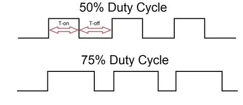
PWM, a better design
The relays and charge pumps are a short-term solution. Longer term, I would like to fabricate a custom Raspberry Pi add-on board for this project. The design would apply a DC signal to the valves and then use pulse-width modulation to reduce the duty cycle to about 70%. The PWM circuit quickly switches the power going to the solenoid between an on and off state, and by varying the ratio of on to off, it controls the average amount of power delivered to the circuit.

I successfully built something like this a few years ago with the MAX7316 LED Intensity Controller in an automotive application. Here is another example of someone who has done this with a DRV103
How about that heat
That’s enough talk for now on output devices. In my next article, I will cover how I detect environmental information like temperature, humidity, rain, and even how much water we have in our storage tank.

This post is part of the Off-Grid Farm Automation with Raspberry Pi series — a full DIY walkthrough of building a self-hosted system for sensors, valves, and automation, no cloud required.