There are several ways to connect peripheral devices and sensors to a Raspberry Pi. My last article was about the Dallas 1-Wire® protocol. In this article, I would like to discuss the Inter-Integrated Circuit Protocol, or as it is more commonly called, I2C.
I2C was introduced by Philips Semiconductors (now NXP) in 1982 as a low-cost communication method for integrated circuits in devices like TVs and radios. The goal was to make it economical for a master device, such as a microprocessor, to interact with several slave devices, including memory chips, sensors, and displays, over short distances, often within the same board or intra-board setups.
By the early 1990s, I2C gained traction beyond Philips, establishing itself as one of the standards for low-speed peripheral communication in embedded systems. Eventually, an official I2C specification was drafted. By the 2000s, the patent on the protocol expired, and it became an open standard.
Over the years, the protocol has evolved from transferring bits from board to board at 100 kbps to supporting speeds up to 5 Mbps and thousands of devices via 10-bit addressing. However, Raspberry Pi’s I2C speeds are limited to no more than 400 kHz, and it does not support clock stretching.
While many serial protocols exist and serve different purposes, I2C stands out for its cost-effectiveness, making it particularly popular for Raspberry Pi and Arduino platforms.
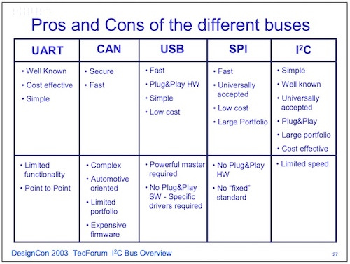
While researching this article, I was delighted to find this document offering a thorough overview and comparison of various serial buses, such as USB, CAN, UART, SPI, and I2C.
Each slave device has a distinct 7-bit address. In some cases, the device addresses can be configured using jumpers, but more often, they are hardcoded into the device and cannot be changed. Unfortunately, there is an overlap of I2C device addresses, as illustrated by this list of known device addresses.
According to the I2C spec, it should be possible to programmatically obtain a 24-bit ID from each device, which should identify the manufacturer, part, and revision. However, I have not yet succeeded in doing this.
The overall goal, though, is that one should be able to just ‘clip’ onto the I2C bus without needing extra external interfacing. What I want to show is that although it can be a bit more complicated than that, we can still do a lot with it.
The devil is in the details.
For most projects, I2C works well. You can find a variety of boards from places like SparkFun or Adafruit. You can plug it together. Download some code snippets in Python, and off you go.
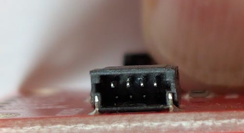
Both companies use 4-pin JST SH 1.0mm connectors. SparkFun calls their system Qwiic, and Adafruit calls it STEMMA. Rumor has it that there were other variants. While connectors are interchangeable, Qwiic only works with 3V devices, while STEMMA accommodates the broader 3 - 5V voltage range. Part of the mismatch is that the Arduino uses 5V logic levels, while the Raspberry Pi uses 3V. You will undoubtedly damage the Raspberry Pi if you attempt to hook up a 5V device with some form of logic-level converter, like a BSS138 FET or TXB0108.
However, on the farm, I have repeatedly discovered that JST SH 1.0mm connectors don’t tolerate the conditions well. They get banged around, bent easily, broken off, and sometimes insects like to nest and pack them with mud.
The tiny JST SH 1.0mm connectors
I needed a more robust solution for our farm automation project.
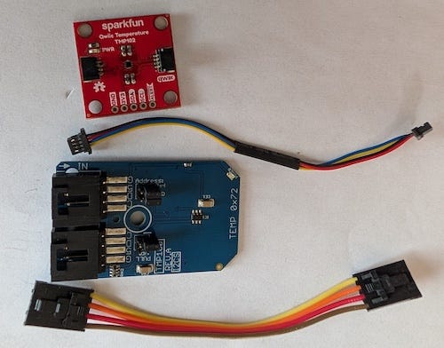
When positioned side by side for comparison, it becomes clear how much more robust the NCD device is. I noticed the quality of the PCB and the soldering is notably more professional.
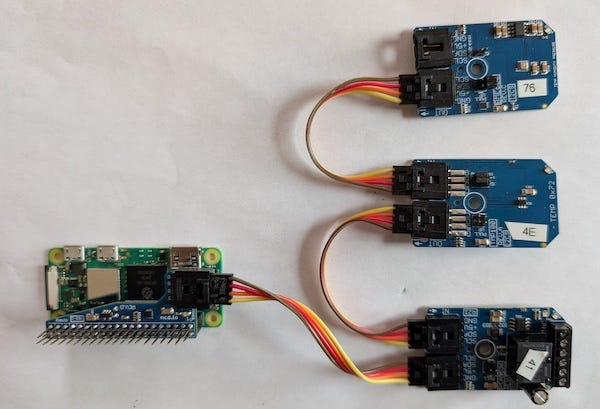
Comparing the Qwiic vs NodeLynk I2C Temperature Sensors
Connecting the Raspberry Pi to nodeLynk requires a logic-level converter, with six different versions available from NCD. However, the 5V system facilitates longer cable lengths due to the larger voltage differential.
Raspberry Pi Zero W attached to nodeLynk devices.
I will say that the NCD parts are a bit more expensive than SparkFun or Adafruit, but these parts will be used in an agricultural environment, not a lab.
Protecting from Electrostatic Discharge
Out here on the farm, I keep learning the lesson that I need to protect my electronics from the electrical surges and electrostatic discharge (ESD) from those fun Arkansas lightning storms.
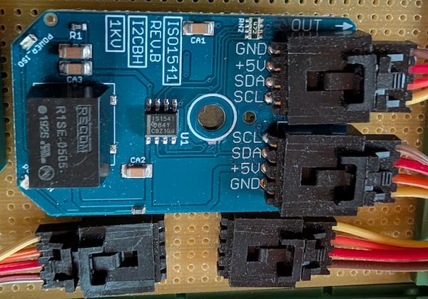
We can do a couple of things to reduce the impact of electrostatic discharge by directing the high-voltage transients picked up by the cables carrying I2C signals and power to a safe route, such as GND, rather than allowing them to flow through the Raspberry Pi and its subsystems.
One way to do this is to isolate the I2C signals and power using a TI ISO1541 on the SCL and SDA signals. This chip gives us about 2.5 kV of isolation. We can also use an isolated DC/DC converter like a RECOM R1SE-0505 to protect the power system.
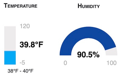
One of the things that my farm automation system does is monitor the temperature and humidity in a walk-in cooler, which we use to preserve our vegetable harvest before the farmers’ market.
Temperature and humidity in the walk-in cooler.
The SHT-25 environmental sensor in the cooler is about 30 feet from the Raspberry Pi. I2C wasn’t designed for this distance. The cable to the sensor has the ability to store electrical charge. This is called parasitic capacitance, which restricts the speed at which a signal going through the cable can be reliably received. At a frequency of 100 kHz, the effective range of I2C can vary between 1 and 10 meters, which is pushing it for where I need to place the sensor.
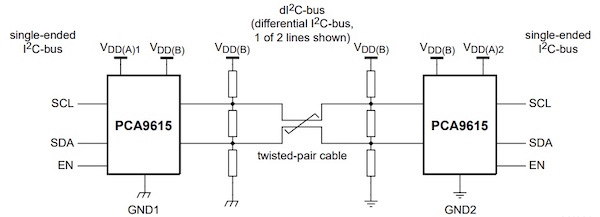
Rather than slow down the Raspberry Pi I2C speeds, I used a technique often employed in industrial control systems to solve this problem. I used a circuit to convert the individual I2C signals into differential pairs.
We can use a chip like the PCA9615 to convert the SCL and SDA signals into a pair of differential signals: SCL+, SCL-, SDA+, and SDA-. Not only can they be reliably sent over a longer twisted-pair cable like CAT5, but they also have higher ESD immunity, and the device can be hot-swapped without damaging the Raspberry Pi.
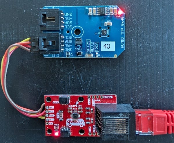
Back when I was building a standby power system for my Oregon well pump, I used a SparkFun QwiicBus EndPoint to communicate with the battery box temperature sensor. Examining the schematic, I see that the design of this board is quite ingenious. Not only does it include a PCA9615, but it also has an RJ-45 connector, which is perfect for CAT-5. And even though they designed it for the Qwiic system, Sparkfun was thoughtful enough to bring the I2C signals and power out to solder through holes.
I checked the data sheet and verified that the PCA9615 can support 5V I2C signals. Then all I had to do to make this work was cut one of the NCD nodeLynk cables and solder it to the SparkFun Endpoint.
Nodelync to Differential I2C hackery
What’s Next
In my next article, I’ll discuss details about the I2C sensors I chose and some tips about how to code I2C on the Raspberry Pi.
I missed a typeo it seems, I called NCD a startup, what I meant was it was a gem the a great startup story. I love when I see a people successful in doing something they love


Here's the article where I discussed building my own board to do these things. https://open.substack.com/pub/vinthewrench/p/raspberry-pi-internet-of-things-part-2a8?utm_source=share&utm_medium=android&r=xxlht
I missed a typeo it seems, I called NCD a startup, what I meant was it was a gem the a great startup story. I love when I see a people successful in doing something they love