
Raspberry Pi Internet of Things - part 5
Reading Environmental Data with I2C

In this article, I want to explore how I collect environmental data for my farm automation. So far, I have had huge success with the 1-Wire DS18B20 sensor for measuring soil temperature. It is highly suitable for agricultural applications, and you can find environmentally sealed versions that are cheaply available. But I’d also like to gather data about humidity in the atmosphere as well as in the greenhouse and walk-in cooler. I have seen 1-Wire sensors available, such as the DHT22, that read both humidity and temperature, but so far, I haven’t found any suitable for outdoor use.
My previous article covered how to interface I2C with the Raspberry Pi. Chances are that I will likely need to monitor additional parameters that are only available in I2C sensors. Let’s start by discussing the devices that I currently support in my Raspberry Pi Internet of Things project.
At this writing, I have written plugins for the following I2C devices:
TMP10X - Low-Power Digital Temperature Sensor
SHT25 - ±1.8% Digital humidity and temperature sensor
SHT30 - Digital humidity and temperature sensor with filter membrane
BME280 - Temperature, Humidity, and Pressure Sensor
ADS1115 - 16 bit Analog-to-Digital Converter
MCP3427 - 2-Channel 16-Bit Analog to Digital Converter
Temperature
There is a considerable number of I²C-compatible temperature sensors on the market. The TMP10x family from Texas Instruments is probably one of the most commonly used ones. This lineup includes TMP100, TMP101, TMP102, and TMP1075. Depending on the model and mode, they can function within a temperature range of -55°C to more than +125°C. There are a few notable differences between the chips worth mentioning:
TMP100 - 3.6 V or 5V device, be configured for up to eight I²C addresses, 0x48- 0x4F
TMP101 - identical to the TMP100 but only supports three addresses, 0x48,0x49,0x4A
TMP102 - 3.6 V device, four addresses, 0x48, 0x49, 0x4A,0x4B
TMP1075 - supports 32 I²C addresses
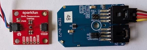
In my projects, I have used the Qwiic-compatible TMP102 board from SparkFun and the TMP100 board in nodeLynk format from National Control Devices.
For this project, I prefer the nodeLync board for the reasons I outlined in my previous article.
Temperature and Relative Humidity
I've had great luck using a couple of I²C-compatible devices to monitor relative humidity, temperature, and even air pressure.
I first experimented quite a bit with the Bosch BME280 sensor. The BME280 is a 3-in-1 environmental sensor measuring temperature, humidity, and barometric pressure. This device is very popular in consumer weather stations. Bosch even provides some sample code online that demonstrates how to get pressure, temperature, and humidity readings. I was able to decipher and port their code fairly easily for my own BME280 piotserver plug-in.
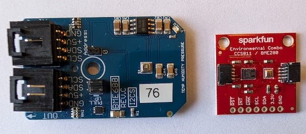
National Control Devices offers a BME280 mini module in nodeLynk format, and Sparkfun has a Qwiic-compatible BME280 board as well. While testing both boards, I often found discrepancies in the BME280’s temperature reading. I have been told that this is possibly due to self-heating from the humidity sensor, and that proper packaging might correct this.
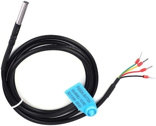
On the other hand, I had a lot of success with the Sensirion SHT30-DIS-F temperature and humidity sensor. It does not have a barometric pressure sensor like the BME280, but I wasn’t planning to use it for weather forecasting. However, what it does have is appropriate packaging for farm use. The DIS-F variant comes in a metal filter container that offers protection against water, dust, and dirt.
I was also pleased to discover that Sensirion had taken the time to publish a few outstanding application notes on their website. There was one on the Physics of Water Vapor, an explanation of humidity formulas, and sample code.
I found an SHT-30 on Amazon, packaged in a waterproof assembly with solder lugs for less than $20. The only downside to it was that the I²C address was fixed at 0x44, making using multiple devices a chore.
Unlike the BME280, the temperature readings were consistent across devices. Another a notable feature of the Sensirion product is that every device comes with a distinct serial number. This might come in handy for tracking failures.
If you needed to take readings from multiple locations, a simple option would be the mini-module from National Control Devices. They have both SHT25 and SHT30 versions available in nodeLync format. The NCD SHT30 has a jumper to allow you the option of selecting address 0x44 or 0x45.
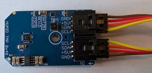
The SHT25 has a fixed address of 0x40. Note that since the SHT-25 is a 3.3V device, NCD included a voltage level shifter circuit on their board to make it NodeLync compatible.
By using the NCD SHT30 and SHT25, I was able to connect two more devices on the same bus. I placed the SHT30, the one housed in a metal casing (0x44), in the outdoor garden, and the SHT25 (0x40) in the walk-in cooler. That left me one more slot for the SHT30 at address 0x45. If you wanted to add more than that, you would have to use a multiplexer like a TCA9546A to share the same I²C address.
There are certainly other options out there besides the BME280, SHT30, and SHT25 for tracking temperature and humidity. Although NCD, Adafruit, and Sparkfun offer extensive selections, at this time, I found these to be more than sufficient for my needs.
Measuring Water Level
One more parameter worth mentioning is water level; I don’t mean rain detection; I’ll discuss that in a separate article—rather, the amount of water in a tank or cistern.
If you recall, a few months ago, I wrote about pumping water from the creek to fill a water tank. The system used a mechanical water level indicator. Since the tank was about half a mile away, I had to drive to the other end of the farm to read the tank level. As it turned out, the tank outlet pipe cracked during the winter freeze, which taught me a lesson about how cold it gets here. I guess it would have been nice to know earlier what was going on with the tank.
This was a good opportunity to take advantage of the knowledge I had gained previously, building a system to measure the water level remotely. Back in Oregon, I installed a 2000-gallon underground water storage cistern to cover us during the dry summer months. We often ran short of water because of the lowered water table. Nothing to do with climate change, Oregon has a long recorded history of drought conditions. I suspect this was attributed to the marijuana growers trying to make a quick buck, despite the environmental impact.
As this water was also essential for firefighting, knowing its level was crucial for scheduling a water truck way ahead of time. I experimented with several designs to monitor the cistern water level and found that a TL231 pressure sensor worked best.
As I stated in my write-up, TL231 transmits a measurement of water pressure over a 4-20 mA current loop. I built this monitoring system during the supply chain failure of the Wuhan/Fauci virus lab leak, and I had to use the parts I could find at the time.
For this redesign, I got hold of the 4-20 mA Current Loop Receiver board from the NCD store. It was perfect for my needs. NCD integrated an ADS1115 Analog to Digital Converter, an INA196 current shunt monitoring chip, and a power supply onto a single board. This significantly simplified the circuit construction; I only needed to connect the TL231 to the board.
Writing I²C code to get data from the ADS1115 wasn’t too difficult at all.
The only challenge was to figure out how the raw voltage level that the ADS1115 reported values equated to the 4- 20mA range.
To be fair, NCD documented that at 4mA, the raw ADC value will be around 6,430, and at 20mA, around 32,154. But without placing the sensor in the tank, I couldn’t be sure if my code functioned correctly.
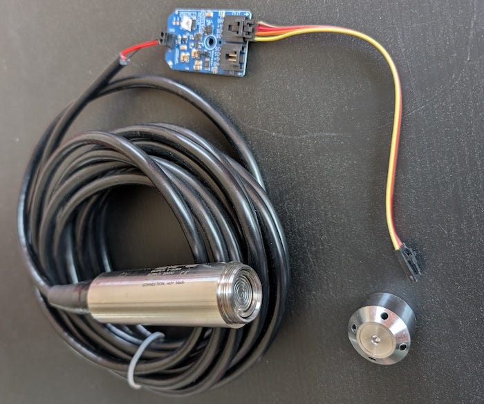
While pondering this problem, I noticed that the TL231 had a removable cap and that the sender underneath resembled a button.
Hmm!
I found that if I put a milli-amp meter in series with the connection as I pressed on the pressure sender, I could cause the current to vary between 4 and 20mA.
Thus, with my finger off the button, the equivalent of ambient air pressure at the bottom of an empty tank, I got 4.5mA at the ammeter, and a reading of 7,500 at the ADS1115 data register. Then I pressed hard on the sender, I got 21.5mA at the ammeter and maxed the ADS1115 at 32,767 (0x7FFF).
I need to determine three constants using the same formula that worked for me for the cistern level.
tankEmpty = which I already know is the same as air pressure, 7,500.
tankFull = This requires me to drop the sender to the bottom of a full tank.
tankGals = I already know it is 2000 gallons.
Then, given the rV = raw data from the ADS1115 data register, we can solve for the volume of water left in the tank.
Percent = ((rV - tankEmpty) / (tankFull- tankEmpty)
Volume = Percent * tankGals
Or expressed as code:
uint16_t valFull = ??? ;// Tank full
uint16_t valEmpty = 7500;// Tank empty
uint16_t tankGals = 2000;
// pin rawData within range
if(rawData < valEmpty) rawData = valEmpty;
else if (rawData > valFull) rawData = valFull;
float volume = (float((rawData - valEmpty))
/float(( valFull - valEmpty))) * float(tankGals);It’s not the heat, it’s the humidity.
Another important thing to keep track of around the farm is whether it rained. This is a topic that requires its own dedicated article.

This post is part of the Off-Grid Farm Automation with Raspberry Pi series — a full DIY walkthrough of building a self-hosted system for sensors, valves, and automation, no cloud required.