Today I want to talk about the humble actuator. Actuators are the unsung heroes of the electromechanical world—always working, rarely appreciated. These devices convert electrical energy into linear mechanical motion. If sensors are the nervous system, actuators are the muscles. They show up anywhere something needs to push, pull, lift, clamp, or position: robotics, CNC machines, power seats, industrial automation, gate openers, and yes—even chicken coop doors.
Actuator used to open entrance gate
But linear motion is not new. The roots go way back—over 2,200 years—to Archimedes’ screw in ancient Greece. While he used a helical shaft inside a tube to lift water for irrigation, the principle was the same one we use today in linear actuators: Rotate a threaded shaft - convert rotation into linear motion.
Fast forward to the Industrial Revolution, when steam pistons and later hydraulic cylinders became the powerhouses of industry. Hydraulics, in particular, have earned their place, they are unmatched for raw pushing force and still dominate heavy machinery like excavators, backhoes, presses, and aircraft landing gear. If you need to move tons, hydraulics are still king.
However, hydraulics come with trade-offs: pumps, hoses, valves, fluids, and higher maintenance. As control systems evolved and automation spread, a lighter and cleaner alternative emerged: the electric linear actuator.
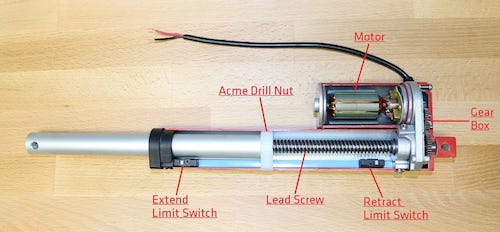
Today, when someone says “actuator,” they usually mean an electric linear actuator: a DC motor turning a lead screw or ball screw, converting rotary motion into precise linear motion. Inside a typical electric linear actuator, the mechanics look something like this:
A DC motor turns a gearbox, which drives a lead screw (often an ACME or trapezoidal thread). A drive nut—sometimes called a drill nut—rides along the screw as it turns. That nut is mechanically linked to the actuator rod (shaft), which is pushed or pulled in a straight line as the screw rotates.
actuator cutaway
In some designs, the nut is fixed and the screw moves; in others, the screw is fixed and the nut moves. Either way, the screw converts rotational motion into linear motion—the same idea people have used since Archimedes—but now wrapped in metal with ball bearings and precision machining.
The result is simple: when you apply power to the DC motor, the actuator moves. The direction of motion depends on polarity. Apply current one way, the motor spins forward and extends the rod. Reverse the polarity, the motor spins the opposite direction and retracts the rod. There’s no magic in it—just DC motor physics and screw mechanics working together to turn electrons into motion.
Doing the Chicken Dance
While I’ve used linear actuators before in automotive projects, one of my more practical and entertaining uses for them was in my backyard chicken coop.
Chickens are tasty and predators know it. That means the coop door needs to close securely at night and open again at sunrise, whether I’m home or not. So I automated it.
What started as a simple idea turned into two generations of engineering experiments: the first built around an Arduino, and the second upgraded to a Raspberry Pi for more flexibility and remote control.
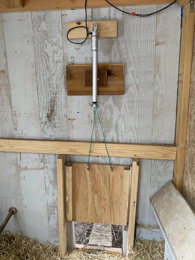
The mechanics were simple. The coop door was just a piece of ¾″ plywood sliding vertically in a pair of drawer slides. A Progressive Automations PA-14 linear actuator mounted above the door provided the muscle. Instead of mounting the rod directly to the door, I attached it with some stainless steel cable, which gave the system a little flexibility and reduced binding if the door wasn’t perfectly aligned.
When the actuator extended, it lifted the door open. When it retracted, gravity did the rest and the door closed tightly to keep predators out. A simple idea—but it worked.
The weight of the door made it nearly impossible for a raccoon to lift from the outside, but the cable connection had a useful side effect: if a chicken was slow and happened to be standing under the door as it closed, it wouldn’t get crushed. The wire provided just enough give that the bird would get pushed aside instead of pinned, a simple but important safety feature. This mechanical fail-safe also eliminated the need for an electronic jam detection system in that project. Sometimes physics trumps circuitry.
In my earlier Arduino article, I described the basic circuit I used to control the PA-14 actuator.
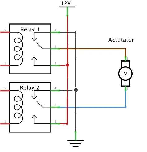
The PA-14 incorporates a built in set of limit switches. All we needed to do to operate it, is to run DC current though it one way to open and then reverse the polarity to close. A simple way to accomplish this is by using a pair of SPDT relays in an H-bridge configuration as illustrated in the diagram below. The actuator motor will spin one direction or the opposite depending on which relay is activated. This translates into up or down in our application
Using two SPDT relays to implement an H-Bridge
The H-Bridge
The circuit I used was based on the classic H-bridge, a motor control topology that reverses a DC motor by switching the polarity of the voltage across it. The idea predates semiconductors and was originally built using electromechanical relays, but it became much more practical in the late 1960s and 1970s with the rise of power transistors. By the early 1980s, H-bridge designs were showing up everywhere—from industrial control systems to robotics research papers and even hobbyist magazines like Popular Electronics and BYTE.
Before dedicated motor driver chips existed, H-bridges were built from discrete bipolar transistors, and while that approach worked, it had plenty of pitfalls: thermal runaway, poor efficiency, slow switching, and frequent magic smoke incidents. Many electronics experimenters learned the hard way that building an H-bridge out of four TIP120s or TIP122s was a terrible idea, as the excellent article “Do Not TIP!” from Tom Jennings explains in painful detail. Those early bridges lacked current sensing, protection, and any kind of intelligent control.
By the mid-1980s, integrated H-bridge motor drivers began to appear, making things easier. Parts like Unitrode/TI’s L293/L293D and later ST’s L298 turned bidirectional DC motor control into an off-the-shelf capability. These chips brought flyback protection, enable logic, and thermal shutdown into a single IC. They were a huge step forward—but they were still “dumb” drivers. They could push power, but they had no awareness of load, motion, or trouble conditions like jams or stalls.
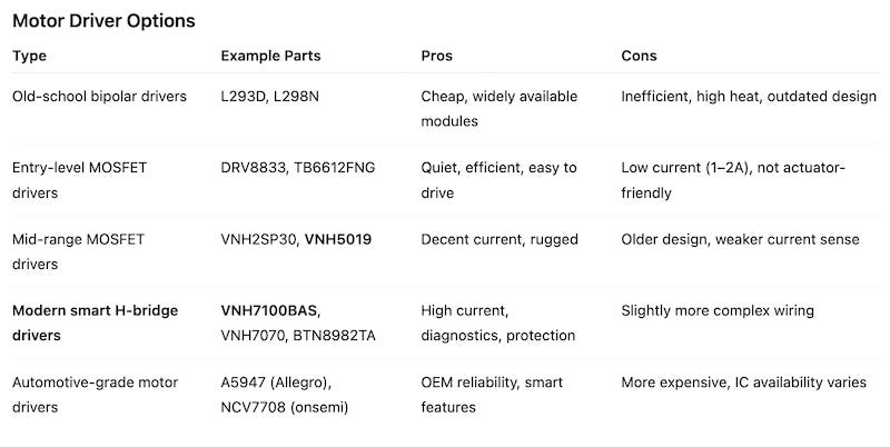
Modern Motor Driver Options
Motor control has come a long way since the days of relay H-bridges and stacks of TO-220 transistors. Today, there are dozens of integrated H-bridge driver ICs designed for everything from tiny gear motors to heavy industrial actuators.
Most fall into a few broad categories:
While there are a lot of motor drivers available today, but not many that are truly suited for linear actuator control. Actuators place much harsher electrical and mechanical demands on a driver. They can hit hard end stops, stall under load, draw large surge currents, and operate in environments where reliability actually matters.
That immediately ruled out older or underpowered drivers like the L298N modules or the DRV88xx breakout boards. After comparing options from Infineon, STMicroelectronics, and TI, I chose the VNH7100BAS - automotive fully integrated H-bridge motor driver. It offers high current capability, low MOSFET on-resistance, and built-in protection against overcurrent, overheating, and under-voltage.
In addition, theVNH7100BAS also provides an analog current sense output, which makes it possible to detect stalls, overloads, or jam conditions in software. It handles 12V systems comfortably and accepts both 3.3V and 5V logic, making it easy to interface with microcontrollers and single-board computers.
Which leads me to my other design requirement: I wanted a motor controller that could be controlled over I²C, so it would integrate cleanly into my PioT (Pi Internet of Things) ecosystem. I use I²C extensively because it allows multiple intelligent modules to share the same two-wire bus, each with its own address. That means I can run multiple actuator drivers from a single Raspberry Pi without burning precious GPIO pins or building a wiring nightmare.
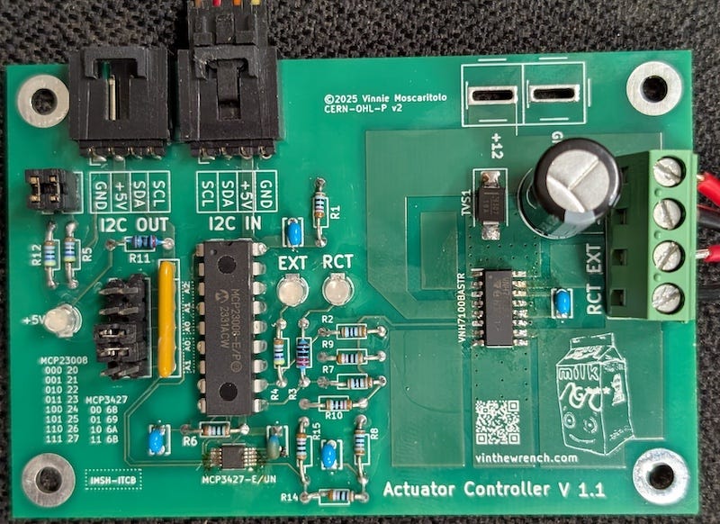
The Actuator Controller board
With those requirements in mind, I took a bite out of the excrement sandwich that is KiCad and designed a motor control board specifically for linear actuators.
Most motor driver boards are built for small DC motors on hobby projects, not for pushing around real mechanical loads, so they skimp on things like protection, sensing, and control. This board doesn’t try to be clever or fashionable. It just does the job: drive an actuator forward and reverse, monitor the load, and shut down safely if something binds.
And because I occasionally need to run more than one actuator, it’s controlled over I²C, which means I can chain multiple boards together on the same bus instead of burning a pile of GPIO pins.
For I²C integration, the board follows the nodeLync wiring standard, so it can sit on the same 4-wire bus as my sensors, display modules, and interface boards and become stackable network devices instead of one-off peripherals.
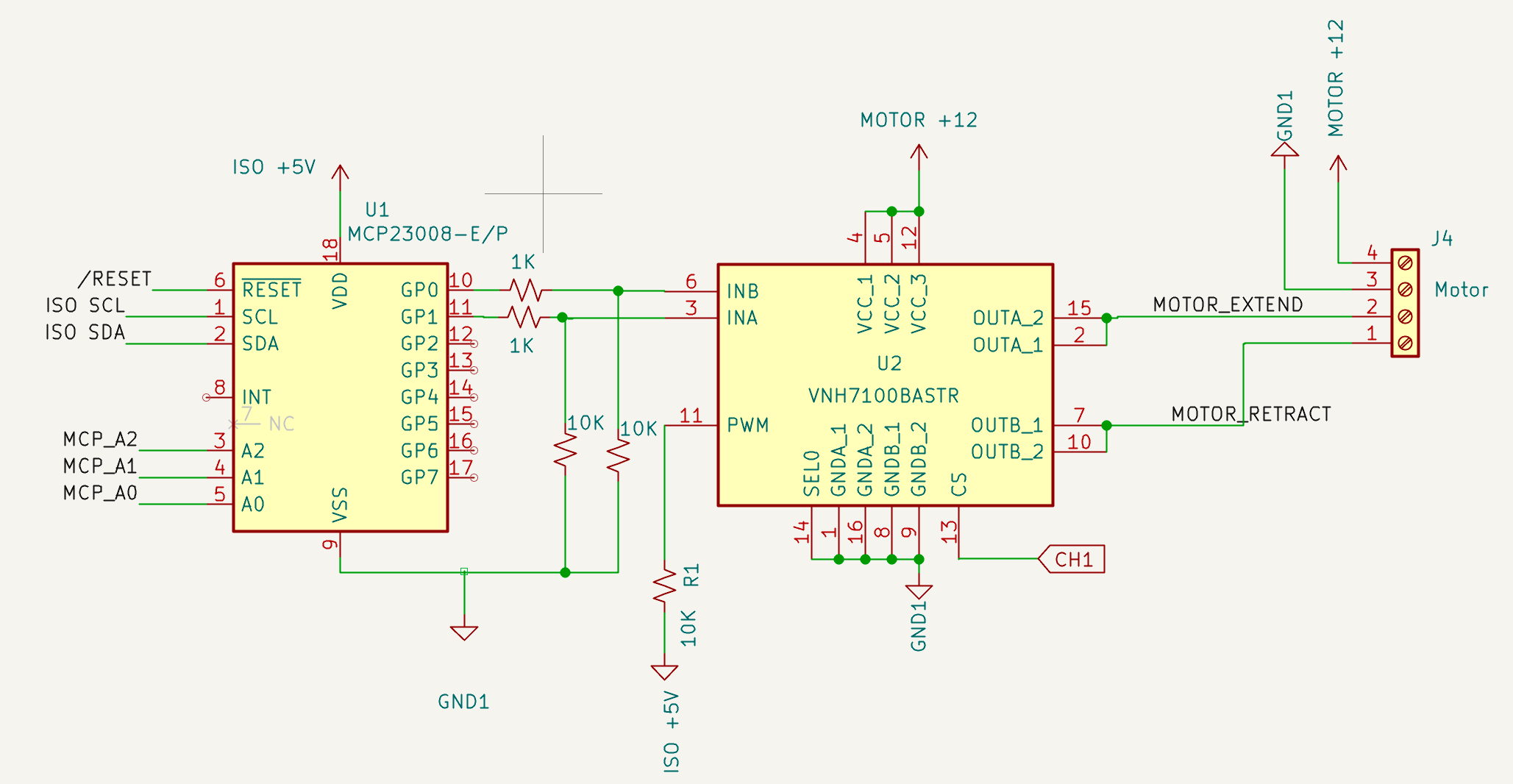
The motor is driven by a VNH7100BAS H-bridge, which reverses the polarity of the 12 V supply to extend or retract the actuator. The actuator connects to the screw terminal labeled MOTOR_EXTEND and MOTOR_RETRACT, which are the two bridge outputs (OUTA and OUTB).
The driver is powered from the 12 V motor rail (MOTOR +12) and referenced to GND1. Its three supply pins are tied together as recommended to share current.
The VNH7100BAS gives us a protected H-bridge with clean forward/reverse control. The direction control comes from two logic inputs:
INA – forward
INB – reverse
Both inputs have 10 kΩ pull-down resistors so the actuator stays off by default. Driving either input high runs the motor in that direction; driving both low disables the bridge.
Driving both INA and INB high will put the H-bridge into brake mode. This design doesn’t use that feature and it can be disabled by tying the PWM high through a 10k pull-up. Linear actuators don’t need electronic braking—they already stop mechanically at their internal limit switches.
The INA and INB control signals come from an MCP23008 I²C GPIO expander, which lets the motor be driven by any I²C master. Only two GPIO pins are needed for direction, but I chose the MCP23008 because it offers multiple selectable I²C addresses, making it easy to use more than one actuator board on the same bus..
VNH7100BAS and MCP23008 I²C to motor interface
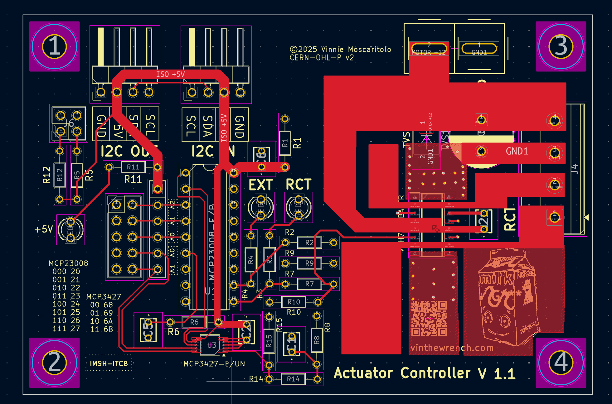
The VNH7100BAS can move real current, which means it can also dump real heat, and ST’s datasheet is very clear about the cure: copper. They provide thermal data showing how much board copper is required to keep the device alive under load, so this layout follows that guidance. The entire right side of the PCB is basically a heatsink, it’s intentional mass of large copper pours tied to the driver’s thermal pad and ground pins, stitched with vias to the bottom layer to spread heat. The wide motor traces aren’t just about current handling; they also act as thermal mass. No external heatsink is required because the PCB itself is doing the thermal work.
A substantial amount of copper is dedicated to the VNH7100BAS heatsink
Power for the actuator can come in two ways: through the main screw terminal block (J4) or via an optional Anderson Powerpole connector. I added the Powerpole footprint because these connectors are common in robotics and amateur radio, and they handle current and vibration better than most PCB terminal blocks. Both inputs feed the same 12 V rail, so you can use whichever connector suits your wiring style—or wire both for daisy-chaining power between boards.
Although not shown in the above diagram, the 12 V rail also includes basic protection for inductive loads: a TVS diode clamps voltage spikes from long cable runs or abrupt motor shutdown, and a pair of capacitors (electrolytic for bulk energy + ceramic for high-frequency noise) stabilize the supply.
The logic side of the board runs on an isolated 5 V rail (ISO +5V), which keeps I²C communication clean even when the motor wiring gets noisy. Power and logic grounds meet at a single point near the driver to prevent ground loops while still giving the H-bridge a solid current return path.
Detecting Stalls and Overcurrent
Linear actuators are simple to drive but difficult to monitor. Most do not provide position or load feedback, and even units that include internal limit switches only stop travel at the ends. They do nothing if the actuator binds, jams, or stalls in the middle of its stroke. When that happens the motor current rises quickly and, if not detected, it can damage the actuator or the driver. For that reason this design includes current monitoring so the controller can detect motion, recognize overload, and shut down safely when necessary.
The VNH7100BAS has a built-in current sense output, which makes it easy to monitor the load on the actuator without adding a shunt resistor or amplifier. Its CS pin outputs a voltage that is proportional to the motor current. That signal tells us what the actuator is doing. If the current rises, the actuator is either pushing a heavy load or approaching a stall. If the current suddenly drops to zero, it has probably hit an internal limit switch or the load has been removed. By watching current in real time, we can detect motion, confirm direction, and shut down safely when something goes wrong.
Some designs use the CS pin as a simple fault detector by comparing it against a voltage threshold and shutting down the motor if it rises too high. That crude on/off approach makes sense in applications where the load is always the same, like a folding step on a lifted Jeep. Once you know the normal current draw, you can just trip on anything above it.
NOTE: there is a mistake on this board, I misunderstood how the SEL0 (pin14) on the VNH7100BAS needs to be wired. it need to go high when monitoring INA and low when monitoring INB. I’ll spin a fix where I attach the SEL0 to one of the unused MCP23008 gpio pins.
However, I wanted more flexibility than that. By feeding the CS signal into an external ADC, I can read the actual current in firmware and make smarter decisions. That lets me detect gradual load changes, distinguish startup current from a real stall, and apply different limits to different actuators. In other words, using an ADC turns the CS pin from a simple fault flag into useful telemetry.
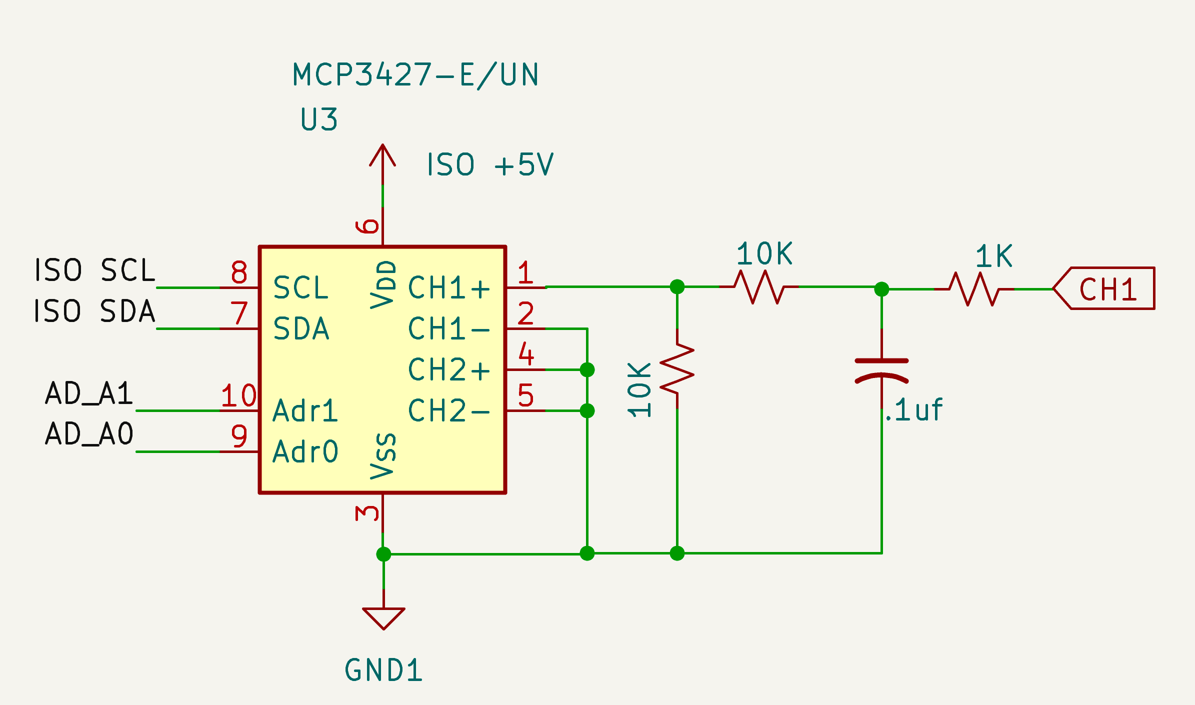
Using the MCP3427 A/D converter to measure actuator current usage.
To read the current sense voltage I needed an analog-to-digital converter. Since the controller communicates over I²C, an external ADC made the most sense for integration. I used the MCP3427, a two-channel delta-sigma ADC. It is accurate enough for current measurement, easy to work with, and supports multiple I²C addresses so more than one actuator board can be used on the same bus.
The current sense output from the VNH7100BAS is usable but noisy because it reflects switching activity inside the H-bridge and changes in motor load. To clean it up I added a simple RC filter: a 1 kΩ series resistor and a 0.1 µF capacitor to ground. This removes switching spikes while still allowing real load changes to pass through.
The CS voltage is proportional to motor current, but it can exceed the safe input range of the ADC. To prevent that, the filtered signal goes through a 10 kΩ / 10 kΩ divider, which cuts the voltage in half before it reaches the MCP3427. Scaling the result back to actual motor current is straightforward in firmware.
The ADC is configured in single-ended mode on one channel to read the filtered current sense signal. I run it in 12-bit continuous conversion mode, which provides a good balance between resolution and sample rate. At that setting the MCP3427 produces a new reading every few milliseconds, which is fast enough to track changes in actuator load in real time without flooding the I²C bus.
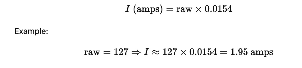
The MCP3427 reports a raw digital value that represents the scaled CS voltage. That number is then converted back to the actual motor current using a fixed multiplier. Because the relationship between motor current and CS voltage is linear, it only takes simple math to get meaningful values.
ith the MCP3427 set to 12-bit mode and using the 10 kΩ / 10 kΩ divider on the CS line, each ADC count represents about 15.4 milliamps of motor current.
That is accurate enough to detect load changes and stalls without any complex math. If more precision is needed, a one-point calibration can be done later, but for actuator control this scaling factor works well as-is.
Once current is available as a real measurement, it can be used to detect end-of-travel stops and mechanical problems. For example, when the actuator first starts moving the current rises briefly, then settles while it moves under normal load. A sudden rise in current indicates a stall or jam, while a sudden drop to zero usually means the actuator has hit its built-in limit switch. Monitoring that pattern allows the controller to shut the motor off before damage occurs.
Build It Yourself
The final result is a compact, reliable actuator controller that speaks I²C, survives real mechanical loads, and does not burst into flames when something jams. It is simple enough to integrate into almost any project but flexible enough for automation, robotics, or vehicle work. The full KiCad design, schematics, firmware examples, and BOM are available on GitHub at:
The design is open hardware under the CERN-OHL-P license, so use it, modify it, or build on it however you like.
This controller will show up again in future projects where I need reliable motion control. Doors, valves, vents, hatches, maybe even a robot gate. It is now a building block in the larger off-grid control system.
I also shot a short test demo of the board driving a linear actuator. You can watch it here: