
A Better Automatic Chicken Coop Door
From Backyard Chickens to 100-Bird Pasture Rotation: Why I Scrapped Two Earlier Controllers and Built a Purpose-Built Ultra-Low-Power Coop Door from Scratch

Project Overview
12 V battery-powered chicken coop door controller with optional solar charging.
Opens and closes the coop door using configurable sunrise and sunset offsets.
Gravity-actuated vertical door with an anti-predator locking mechanism.
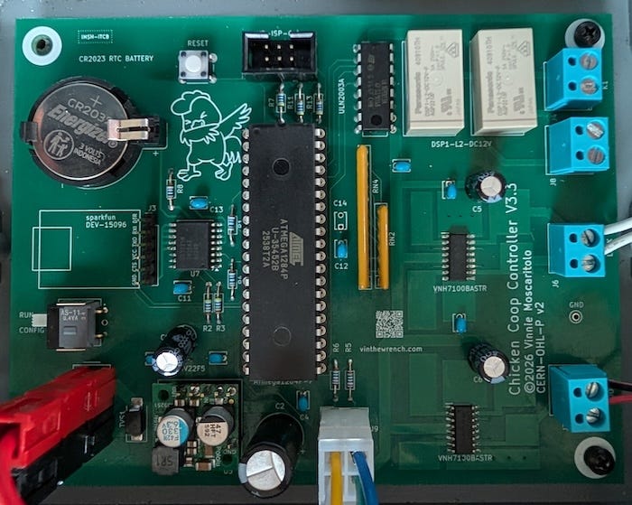
Custom ATmega1284P controller board, about $50 in parts.
Ultra-low-power design with deep sleep current in the microamp range.
Runs without Wi-Fi, cloud services, or internet access.
Complete firmware, schematics, and PCB layout available on GitHub.
Not My First Rodeo
We started keeping chickens when I lived in Oregon. The fresh eggs were nice, but what was nicer was knowing where our food came from. It wasn’t some grand homesteading plan. It was simply a small, practical step toward owning one more piece of our lives.
I think at tops we only hosted about a dozen birds.
And as it turned out, our effort to put distance from disorder, grew into something much bigger. We now run Stella Porta, a small regenerative farm built around naturally grown practices. What began with a few backyard chickens has turned into something more serious, with real production goals, real schedules, and real consequences when things fail.
When we built our first coop, I immediately decided the door needed to be automated. I have zero interest in babysitting chickens. A daily check and egg collection is fine but having the door dictate my schedule isn’t.
Rather than buy automated door, I home brewed my own.
The first version of the controller board used an Arduino variant, driving relay outputs for the door actuator. Although it was fairly simple, it included integrated battery backup to keep the door operating through power failures, and Wi-Fi access that let me adjust parameters over the network.
Around 2022, I revisited the system, moved it to a Raspberry Pi and wrote an accompanying iPhone app. The new controller also scheduled supplemental lighting to encourage egg production during Oregon’s darker and shorter winter.
Naturally I had the inevitable clashes with bears and raccoons seeking a yummy chicken dinner. Well, to be perfectly honest, they had clashes with my rifle. I wasn’t about to let predators dictating my schedule either, so I eventually added an electric-fence relay to the door scheduling system.
Both the Raspberry Pi and Arduino versions of the controller were connected to a coop in a fixed, fenced area, with a stationary nesting box that remained within Wi-Fi range. They only needed limited battery backup because the system was still mostly AC-powered and not truly a standalone design.
Welcome to Arkansas.
Moving to Arkansas changed everything. We’re now set up for more than a hundred birds, running a mobile coop integrated into our cattle and sheep rotational grazing. The coop moves with the pasture. The birds roam, eat bugs, and do chicken things all day, then come back to the nesting boxes to brood and roost at night.
The environment is different too. There is more sunlight here and so the need for artificial light to simulate day extension is no longer necessary. Bears aren’t the primary threat either. Coyotes are, and that problem is handled mostly the old way, with good dogs doing their job.

Mechanically, I kept what works and hardened what needed hardening. The gravity-hung door stays because it’s safe and reliable. But just to be safe, I added a locking bar so a predator can’t lift the door once it’s closed.
Since the pasture rotates, the coop is often well out of reach of AC power, and so power conservation a priority. Solar can top it off, but we won’t depend on it every day. It needs to survive cloudy stretches, short winter days, rain, snow, whatever Arkansas throws at it.
Chickens are simple: they get up at dawn and roost at dusk. They just need a door that follows that rhythm. So the controller doesn’t need to be complicated, it is simply a box that tells a few devices what to do at specific times, then goes back to sleep.
It is also out of Wi-Fi reach, and it’s not worth the luxury of wasting power on it. Any setup and schedule programming can be done in the field. We’re still out there each day collecting eggs, refilling water, and checking on the girls. But once the schedule is configured, I shouldn’t have to mess with it. It should just run on its own.
I have seen some very elaborate coop automation projects on the net. One example is Dave Duncanson’s SmartCoop system in Australia, He uses a Raspberry Pi along with sensors, networking, and extensive monitoring. That system is designed for a fixed backyard coop with reliable power and Wi-Fi access.
My goals were much simpler. I just needed a small controller that opens the door at dawn, closes and locks it at dusk, then goes back to sleep while running from a battery in the middle of a rotating pasture.
Different constraints lead to very different designs.
Scheduling the Door
So how do you decide when it’s time to open and close the door? I have seen it done a couple of ways.
One option is a simple time clock. But that means constantly readjusting for the solar cycle as day length changes through the year.
Another approach is a light sensor. The problem is that light sensors lie. A light sensor doesn’t know what sunrise or sunset is. It only knows how bright it happens to be at that moment, right where it’s mounted. Clouds can turn midday into dusk. Shadows move. Snow reflects light in ways that break thresholds. Headlights and yard lights create false sunrises. Reflections off wet ground or metal siding spike readings at exactly the wrong time.
In a mobile coop, those problems get worse. As the coop moves, its orientation changes. The horizon changes. Mounting angles change. Even a perfectly calibrated sensor becomes unreliable the moment the environment shifts.
On the other hand, sunrise and sunset are predictable events. Given a location and a date, you can accurately and repeatably calculate the time they will occur. If you base your door schedule as a simple offset from those events and it will stay aligned with the season. It won’t drift, it won’t be fooled by clouds or shadows, and it won’t need constant adjustment.
Here comes the Sun
Computing sunrise and sunset from location and date isn’t hard. I don’t know why people overthink this. You only need a few ingredients: latitude, longitude, a reliable (battery-backed) real-time clock, and a little basic solar math.
Latitude determines how high the sun climbs and how long the day lasts, while longitude shifts the time of solar noon relative to your clock.
None of this is new-fangled science. The core ideas go back to the Babylonian and Greek astronomers, notably the work of Ptolemy in the 2nd century AD. Major refinements came in the 1600s and 1700s, as Kepler sussed out the laws of orbital motion. Later refinements added precision by accounting for Earth’s axial tilt. By the 18th and 19th centuries, these calculations were standard in nautical almanacs. Sailors could predict sunrise and sunset reliably anywhere on Earth.
Pro tip: This math has been spot-on for centuries on a round Earth. Flat Earth versions? Not so much.
So here’s how it works.
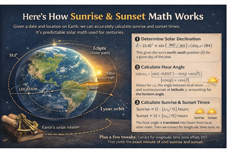
Earth rotates once every 24 hours and orbits the Sun once a year. We know the rate of that rotation, and we can model how axial tilt and orbital geometry change the Sun’s apparent path day by day. Using the trigonometry I describe below, we can write code that calculates the exact minute the Sun crosses the horizon for a given date and location.
We also factor in a standard horizon angle of about 0.833 degrees below the true horizon to account for atmospheric refraction, which bends light slightly, and the upper limb of the Sun’s visible disk, which takes time to fully rise or set.
If you’re curious (or building something similar), here’s the basic math my code runs.
Solar declination (δ) - the sun’s north-south position:
δ ≈ 23.45° × sin( (360° / 365) × (day_of_year + 284) )
(Or a common variant: δ ≈ -23.44° × sin( (360° / 365.25) × (day_of_year - 81) ))Hour angle at sunrise/sunset (ω_s):
cos(ω_s) = [sin(-0.833°) - sin(φ) × sin(δ)] / [cos(φ) × cos(δ)]
where φ = latitude, δ = declination, -0.833° = horizon correction (refraction + sun’s disk).
Then ω_s = acos( that value )Times from local noon:
Sunrise ≈ 12 - (ω_s / 15) hours
Sunset ≈ 12 + (ω_s / 15) hours (Earth rotates 15° per hour.)
Scheduling and State Reduction
Calculating sunrise and sunset turns out to be the easy part of coop automation. The hard part is keeping the system in the correct state when things inevitably go wrong.
A lot of automation systems treat schedules as a series of triggers. At 6:51 AM, fire an “open” event. At 6:03 PM, fire a “close” event. That sounds simple until the power fails, the controller reboots, or someone overrides the system manually. Now the controller has to remember what already ran, what did not, and whether it should try to “catch up.” Miss one trigger and the system is out of sync.
In a lighting system that might mean a lamp stays on too long. In a chicken coop it can mean the door stays open all night. Screw this up and you get dead chickens.
My system takes a different approach.
The schedule does not fire events. Instead, it defines the desired state of each device at every minute of the day. When the controller wakes up or needs to make a decision, it asks a simple question:
At this moment, what state should each device be in?
For example, on a given day the door schedule might look like this:
Solar      Rise        Set
Actual     06:51 AM    06:03 PM
Civil      06:26 AM    06:29 PM

Events:
06:51  OPEN    Sunrise +0
18:18  CLOSED  Sunset +15
That’s it. Two declarative statements: the door should be open after sunrise, and it should close 15 minutes after sunset.
The reducer algorithm looks at the current time and determines which of those two events governs the door right now.
Sounds simple enough. But what happens when we add human interaction?
Say the door is scheduled to open at sunrise and close at sunset. At 3:00 PM, the farmer presses the button and closes the door.
The door state machine does exactly what it should. It unlocks, drives closed, waits for settle, and locks. Everything works.
Now the scheduler algorithm runs again one minute later. It reduces the schedule and sees that the governing event for the door is still the sunrise “open” event. According to the schedule, the door should be open.
The scheduler will immediately command the door to open again.
The system is technically correct, but practically wrong.
So how do we fix it?
We solve it by recording the timestamp of the last manual action. When the scheduler attempts to apply a scheduled state, it passes along the timestamp of the governing scheduled event. If that event occurred before the manual action, it is ignored.
In other words, the schedule cannot override a newer human action. It must wait until the next scheduled phase, such as sunset, before it regains control.
We also run the algorithm clock in UTC, so changes in Daylight Saving Time never shifts events, never touches the solar math, and the only thing that ever changes is how the time is displayed to a human.
The Door Electronics
Now that we know when to open the door, how are we going to do it?
While horizontal sliding doors look simple and convenient on paper. They have some drawbacks.
We used an Omlet automatic door on our temporary coop with just six birds because it was expedient and installed quickly. The design included a safety switch on one side to prevent the door from closing on a chicken, which is a sensible feature.
But then we had an ice storm and the door froze solid.
I had to hit it with a heat gun to thaw the mechanism so the birds could get out. I disconnected it and propped a brick and plywood in its place for the week.
From what I could see, the combination of gears and open slide tracks allowed dust, moisture, and ice to work their way into the mechanism and freeze everything in place.
That experience pushed me toward a different design.
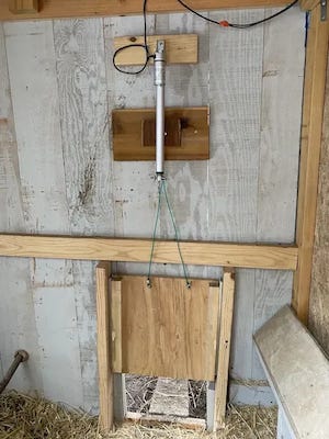
Instead of sliding sideways, my coop doors open vertically. The door is lifted by retracting a cable with an actuator, and gravity closes it again when the actuator extends.
The door itself rides on a pair of aluminum guide rails with slide blocks I picked up at Home Depot. These are linear motion components commonly used in CNC machines, automated equipment, and even some shop-built router or saw sleds where something needs to move straight while staying aligned. In this case they simply keep the door traveling smoothly up and down without twisting or binding. I mounted the sliding mechanism inside the coop so there are no exposed tracks to clog or freeze.
To move the door I used a Progressive Automations PA-14 linear push-pull actuator (now sold as model PA-01-12-56-N-12VDC). It has a stainless steel stroke rod and an IP65-rated aluminum alloy housing, with no exposed spinning parts to gum up in chicken dust or freeze solid during icy Arkansas winter nights, where a stuck door can mean dead birds. The unit also includes built-in limit switches, so it automatically stops at the ends of its travel without requiring additional sensors.
If you want the nitty-gritty on why I chose this device and how to electrically drive it, see my article “The Humble Actuator.”
Working backwards from the actuator, the motor is driven electrically using a VNH7100BAS H-bridge. This chip can move real current, up to 15 A continuous. Which is more than enough for the actuator but also means it can generate real heat under load. The data-sheet is clear about this and recommends providing substantial copper area on the PCB for thermal management.
The Locking Mechanism
A gravity-hung door prevents crushing, but it does nothing to stop something from pushing upward from outside the coop. A determined raccoon or coyote will pull, pry, and test weaknesses for hours.
So the door also needs a way to lock.
I didn’t have to look far for a solution. My automated garage door had already solved this exact problem. When it closes, a steel deadbolt slides into the track, physically preventing the door from being lifted.
That raised an obvious question: what’s actually inside that lock? I opened up a LiftMaster 841LM and, to my surprise, found that the mechanism inside is fundamentally the same as the automotive door lock actuators you can buy for less than five dollars.
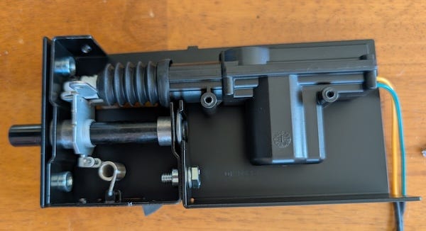
Inside, the mechanism is simple. A small DC motor drives a set of reduction gears that move a sliding linkage back and forth, pushing or pulling a steel bolt into position. When the bolt extends into the strike, any upward force on the door is transferred directly into the frame, not through the motor. Once engaged, the load is carried entirely by the latch. The motor and gear train are no longer holding the door up; the steel latch is.
The motor itself is just a brushed DC motor. Apply current one way and the bolt extends. Reverse the polarity and it retracts. There are no position sensors or smart electronics inside, just a motor and gears. Controlling it simply requires reversing the motor direction, which makes it a perfect job for the same kind of VNH7100BAS H-bridge used to drive the actuator.
Door Motion and Lock State Machine
On the software side, the actuator and door lock are driven by a state machine that manages the motion.
Before any door movement command is issued, the controller first runs a latch-release sequence. This prevents the actuator from jamming if someone has manually messed with the latch.
The door cycle then proceeds as follows:
The controller releases the latch.
The H-bridge is enabled and the actuator begins moving the door.
When the configured travel time expires, the H-bridge is disabled and the motor stops.
The controller waits for a short settling delay.
During a closing cycle this delay allows gravity and the mechanism to settle before the lock engages.
After the delay, the controller sends a lock pulse to secure the door.
This sequence prevents mechanical shock, reduces stress on the latch, and ensures the door is fully seated before it is locked.
This state machine also provides visual feedback by driving a red/green door button LED.
Home brewing the Hardware
Everything up to this point has been logic: schedules, reducers, state machines, sunrise math and motor control. Now it’s time to dig into the electronics that make it all work.
My original coop controller used off-the-shelf parts bolted together, which made it bigger, more complex, and more expensive than necessary.
But at this point, I knew exactly what the system required: the door logic worked, the actuators were dependable, and the scheduling code was solid. There was no good reason to keep using general-purpose development boards.
Since I’ve designed custom electronics and controller boards before, including the irrigation controller running on the farm, I decided to build a small, purpose-built coop controller board. I wanted a microcontroller that could:
Run reliably using its built-in Real-Time Clock (RTC)
Enter a true deep power-down mode with current in the microamp range
Wake cleanly from an RTC interrupt or a button press
Drive a couple of H-bridges and some LEDs
Store configuration data in non-volatile memory
Provide a simple serial port for setup and configuration
Try to keep the parts count under $50.
I also wanted something that was straightforward to develop with modern tools. Plain C or C++. The avr-gcc toolchain. Explicit Makefiles. No hidden build systems, no IDE magic, no framework layers doing things behind my back.
Don’t Vibe Design
Before I go on, I should confess something. I tried to be like the cool kids and take the AI shortcut. Result, I got burned. I asked both Grok and GPT for advice on choosing the proper MCU and RTC, and both recommendations turned out to be the wrong choice. It suggested the ATmega32U4 as the MCU and the PCF8523T as the RTC.
The ATmega32U4 turned out to be a major headache during development. ISP programming would fail intermittently, and troubleshooting revealed that the programmer could back-power the chip through the SPI pins (MISO/MOSI/SCK) especially if I forgot to turn on the MCU’s power supply during debugging.
Current could flow through the MCU’s internal ESD protection diodes, which can stress or degrade (blow out) the chips I/O drivers, particularly the MISO pin, leading to unreliable detection and programming.
The ATmega32U4 was primarily designed for USB-native applications where the chip is almost always powered whenever a programmer is connected via USB. In standalone, battery-powered, or intermittently powered embedded designs, this back-powering issue becomes a chip killer.
By contrast, the ATmega1284P is a simpler, traditional AVR with fewer internal subsystems. In practice it behaves much more predictably when programmed over ISP in battery-powered or embedded systems.
The PCF8523T also turned out to be the wrong choice for this project. On paper it looks fine. In practice it is was a real ball buster.
The main problem is that it depends on an external 32.768 kHz watch crystal. That means crystal selection, load capacitors, PCB layout, and soldering quality all become critical to stable operation. Timekeeping depends on a fragile tuning-fork crystal. In a stationary indoor product that’s manageable, but this controller lives in a coop that gets dragged around the pasture by a tractor. Vibration and shock are routine, and I didn’t want the system’s timekeeping relying on a mechanically sensitive component.
I also ran into power-transition edge cases. During brownouts the MCU could reset while the RTC continued running from VBAT. A large bulk capacitor on the logic rail stretched the MCU’s brownout window just enough to create awkward reset timing, which meant extra software was needed to keep the system synchronized.
None of these issues make the PCF8523 unusable. It may simply be that I didn’t design around it properly. And I bet that in a well-controlled environment it likely works fine. But it demands more care in oscillator layout, power sequencing, and mechanical protection than I want in something that lives outside as farm equipment.
In a tractor-towed coop running from a 12-volt battery, robustness matters more than saving a handful of microamps. So I wrestled back control of the design and went with the DS3231M.
The DS3231M integrates its own resonator and eliminates the need for an external watch crystal. That removes the layout sensitivity and mechanical fragility that come with tuning-fork crystals, and it simplifies the design considerably.
It also includes temperature compensation and an integrated resonator, so the clock maintains good accuracy without external crystal tuning or calibration. Easy-peasy.
A Few More Hardware Details
As mentioned above, I used two VNH7100BAS H-bridges to drive the actuator and the locking device. I added 1 kΩ series resistors between the MCU outputs and the driver inputs, along with 100 kΩ pull-down resistors on the control lines.
The series resistors limit current and protect the MCU pins from transients or accidental contention during power-up or reset. The pull-down resistors ensure the H-bridge inputs default to a known low state if the MCU pins are high-impedance during reset or startup. Together they prevent the motor driver from briefly enabling or changing direction before the firmware takes control.
I tied SEL0 to GND so a low signal on the PWM pin puts the VNH7100BAS into standby, letting the controller shut the driver off completely when the actuator isn’t moving.
For the 5-volt supply I used the Pololu D24V22F5 buck regulator. It’s efficient, compact, and its quiescent current is low enough that it doesn’t hurt sleep current. It takes the 12-volt battery directly and produces a clean 5 volts for the logic.
I even threw in a couple of DSP1-L2-DC12V 12-volt latching relays. They don’t draw holding current, which fits the low-power theme, and they give me some flexibility. Maybe I’ll use them for an electric fence or supplemental lighting. Maybe something I haven’t thought of yet. The relays are driven from the MCU through a ULN2003A driver, a small workhorse chip that has been switching relays and solenoids since the 1970s.
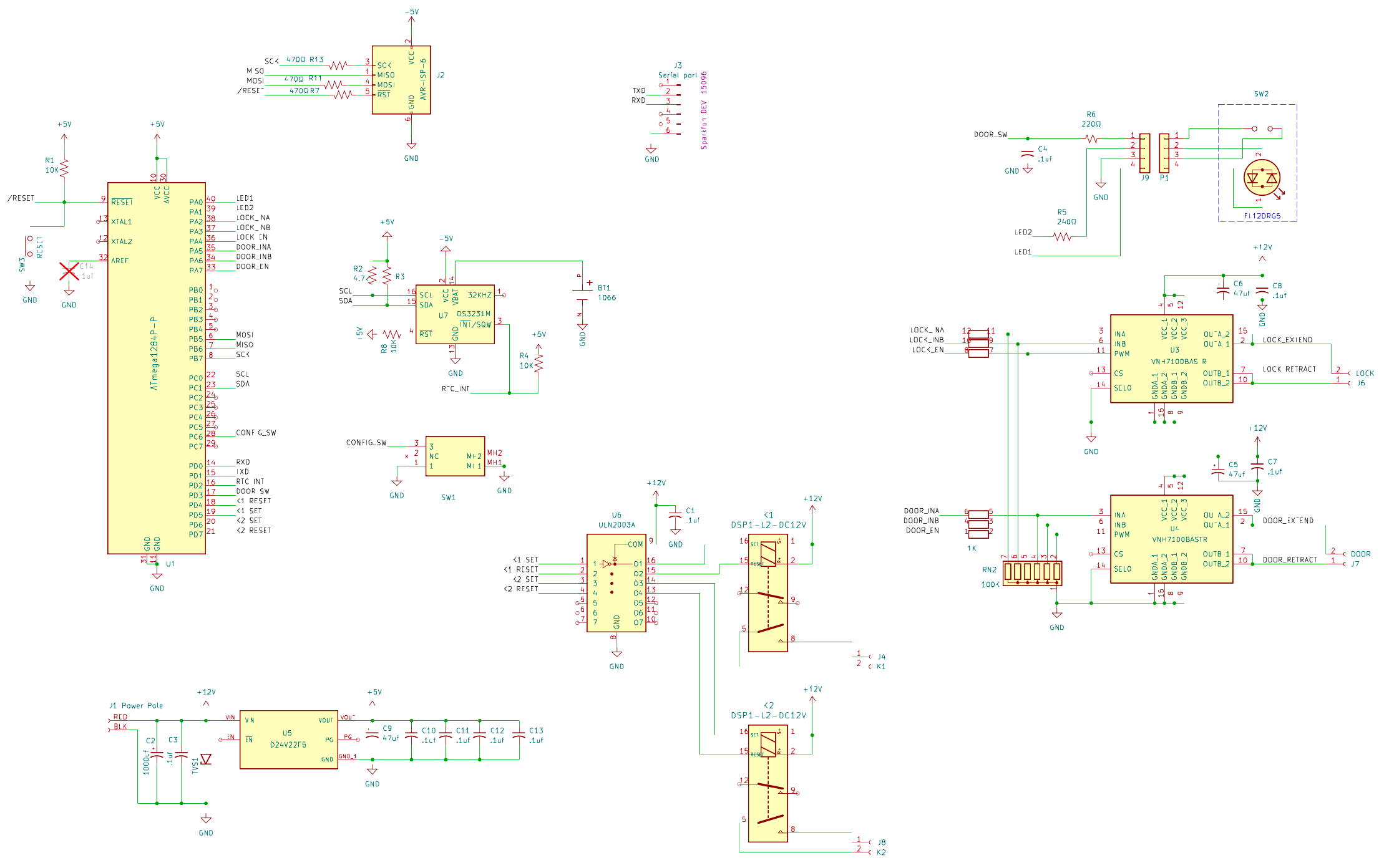
I also added a socket for an optional SparkFun DEV-15096 USB-to-serial module that provides a simple setup console.
When installing the controller, I can plug the adapter in, open a terminal, and interact directly with the firmware. From there I set the clock, enter the latitude and longitude, configure the schedule, and verify that everything is behaving correctly.
Once the system is configured, the adapter is no longer needed and can be removed. The controller runs completely on its own.
The connector also leaves open the option of plugging in a wireless serial bridge later if remote access is useful. But in normal operation there is no reason to leave extra hardware connected drawing power.
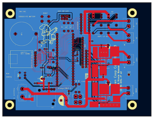
All of this fits comfortably on a 100 × 130 mm PCB. If you’re wondering how I actually make these boards, take a gander at my article : “How Did You Make That?”.
Field Setup, Configuration & Programming
This article covered the design decisions, the math, the hardware choices, and the state-machine logic that make the controller run reliably in a moving pasture.
But design work on the bench is only half the story. The real test is getting it configured and running in the field. That includes:
flashing the firmware onto the ATmega1284P
hooking up the USB-to-serial console
setting your exact latitude and longitude
dialing in the sunrise and sunset offsets
testing the door/lock sequence, measuring sleep current
making sure it survives weeks without touching it.
In the next installment I’ll walk through that entire process step by step. I’ll cover the exact build commands, fuse settings, console configuration, and the commands used to set location and scheduling parameters.
I’ll try and add some power measurements from the finished system and a few troubleshooting tricks that helped shake out early problems.
Like all of my designs, the complete project is already available on GitHub, including the firmware, schematics, and PCB layout.
The software is released under the MIT License, and the hardware design files are published under the CERN-OHL-P v2 open hardware license so others can study it, modify it, and build their own.
If you build one, drop a photo in the comments. I’d love to see how it turns out in your setup.
If you care about how things are made and why they’re built the way they are, you’ll probably like the rest of what I write about. Hitting like and sharing helps real people find the work. The algorithm can go pound sand.
After I published this it occurred to me that I could do a better job explaining the math behind how sunrise and sunset can be calculated from a location and date.
https://www.vinthewrench.com/p/here-comes-the-sun