
Chicken Coop Door, Installed and Running.
Video, installation photos, and command-line setup from the finished coop door controller

In “A Better Automatic Chicken Coop Door,” I explained why I scrapped two earlier controllers, walked through the design process, and showed how the new one works. Now it’s out of the shop, bolted to the coop, and doing real work.
I have since finished the prototyping in the shop and installed the controller in the mobile coop. What follows are a few photos of the finished installation, a short video of the door in operation, and some command-line setup and log output from the actual system.
Installing the Assembly
I built the whole assembly on a sheet of 23/32-inch AdvanTech so the aluminum guide rails would stay aligned. Once it was dialed in, mounting it to the coop wall was just a matter of driving a bunch of screws, and cutting a hole for the door.
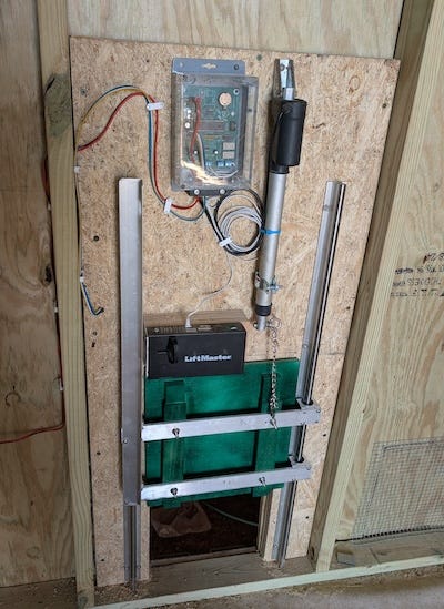
One other small detail: I used a short piece of chain between the actuator and the door, basically like a toilet flapper chain. That gives the linkage a little slack, which helps keep the door from driving hard against anything underneath it, including an unlucky chicken.
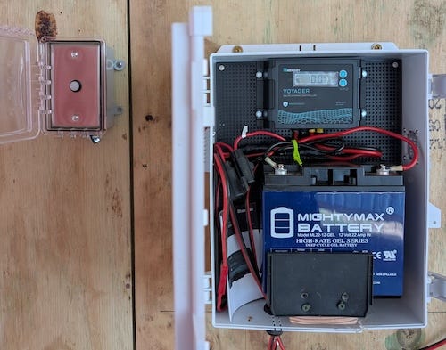
I also built a separate battery box for the power system. It houses the 12-volt battery, a solar charge controller, fuse protection, and the rest of the power wiring in one place. I mounted it outside the coop to make it easier to service and to avoid kneeling around in chicken droppings every time I needed to check or adjust something.
For the charge controller, I used a Renogy Voyager. It is a small PWM unit with a simple display and basic charge management. It is a bit of overkill for this job. It is reliable, straightforward to wire, and stupid easy to set up.
The smaller Wanderer would probably have been a better fit, but I happened to have a few Voyagers sitting around the shop, so one of them went into the battery box.
For the panel, I used an ACOPOWER 30-watt monocrystalline solar panel. The load is low enough that 30 watts is more than plenty for this system.
I also mounted the coop door button and LED combo outside in a weatherproof box with a latching cover. That way, if some Wile E. Coyote type comes snooping around after hours, he has to solve at least one extra puzzle before getting access to the chicken banquet. I was prepared to go further with the predator defense plan, but I needed my anvil.
The Door in Operation
Here is a short video of the coop door in operation after installation. Note the locking solenoid engaging after the door closes.
Programming the Coop
In the earlier article, I mentioned that I added a socket for an optional SparkFun DEV-15096 USB-to-serial module. That gives the controller a simple setup console without needing a display, keypad, or any other nonsense bolted onto the box.
To configure it, I first made sure the CONFIG/RUN switch was set to CONFIG and hit reset. Then I plugged a USB cable from the module into my laptop and connected with:
screen /dev/ttyUSB0 38400That dropped me straight into the console. On first reset, the controller came up with default settings and complained, correctly, that the time and configuration had not been saved yet:
Chicken Coop Controller 2.9.0
WARNING: CONFIG INVALID, USING DEFAULTS
TIME: NOT SET
Use: set date YYYY-MM-DD
     set time HH:MM:SS AM|PM
The first thing I did was set the clock. The easy way is to set the date first, then type in the next minute mark while watching a real clock and hit Return about a second before it rolls over.
> set date 2026-03-26
OK
> set time 16:20:50
OK
Then I verified that the RTC had taken the new time and was reporting sane values. In this case, it showed the clock as valid and confirmed that the time had been set just a few seconds earlier:
> rtc
RTC      : VALID
utc      : 2026-03-26 21:21:12
local    : 2026-03-26 04:21:12 PM
epoch    : 1774560072
since_set: 22 sec (0 days 00:00:22)
After that, I set the rest of the configuration, including latitude, longitude, time zone, DST handling, and the door and lock timing values, then saved it to EEPROM:
> save
OK
>  config
CONFIG (SAVED)

lat  : 34.4653
lon  : -93.3628
tz   : -6
dst  : ON (US rules)
rtc_set_epoch : 1774560050
door_travel_ms : 10000
door_settle_ms : 2000
lock_pulse_ms  : 500
lock_settle_ms : 500
A quick way to verify that the location, time zone, and DST settings are correct is to check the calculated sunrise and sunset times:
> solar
           Rise        Set
Actual     07:09 AM    07:30 PM
Civil      06:44 AM    07:55 PM
If you forget the commands, you can always prompt the system for help:
> help
Commands:
  help      Show help
  version   Show firmware version
  time      Show current date/time
  schedule  Show schedule
  solar     Show sunrise/sunset times
  set       Configure settings
  config    Show configuration
  save      Commit settings
  device    Show or set device state
  door      Manually control door
  lock      Manually control lock
  event     Event commands
  led       Control door LED
  rtc       Show raw RTC state
  sleep     Sleep til next scheduled event
Build Your Own
Like all of my projects, this one is already up on GitHub, including the firmware, schematics, and PCB layout.
The firmware is released under the MIT License, and the hardware design files are published under the CERN-OHL-P v2 open hardware license, so anyone can study it, modify it, and build their own.
If you build one, drop a photo in the comments. I’d enjoy seeing how it ends up in somebody else’s coop.
If you care about how things are made and why they’re built the way they are, you’ll probably like the rest of what I write about. It is not always electronics. Believe it or not, I have been known to jump from baking to perfume to motorcycles without much warning.
Hitting like and sharing helps real people find the work. The algorithm can go pound sand.
Looking good!