

In the earlier article, I wrote about using DS18B20 1-Wire temperature sensors with a Raspberry Pi. These little sensors are handy because they are cheap, digital, and easy to place even in harsh environments. I have had one buried in my garden for about two years now, reliably reporting the soil temperature.
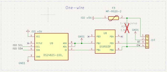
That earlier project started with the simple Linux GPIO 1-Wire path. Later, I moved to the DS2482-100 I²C-to-1-Wire bridge and added better ESD protection and isolated sensor power to handle some of the practical problems that show up when a sensor cable leaves the bench and heads outside.
On the software side, I started with OWFS. OWFS stands for 1-Wire File System. It is a user-space system that makes 1-Wire devices appear as files and directories. That meant I did not have to write code to talk directly to the DS2482-100 or manually issue DS18B20 commands. I could mount the 1-Wire bus and read temperature values using filesystem I/O.
I needed to get the system working and out in the field, and OWFS was a good expedient path. It let me verify the DS2482-100, see the DS18B20 sensors, and get real temperature readings without getting wrapped around the axle writing my own driver.
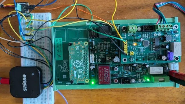
Fast-forward to the present. I had added a couple of custom I²C devices for valve control and power management, and suddenly I found myself debugging all sorts of I²C timing problems, intermittent failures, and general weirdness.
I don’t know for certain whether OWFS caused any of the I²C problems. I suspected the real problem was in the TWI firmware and transaction handling that I let AI help me write. Either way, OWFS was another process with access to the same I²C bus through the DS2482-100, and I didn’t need another piece of code jabbering on the bus behind my back while I was trying to debug it.
Writing reliable I²C/TWI firmware on an AVR like the ATmega88 is not trivial. The AVR has to respond inside the master’s timing window, keep its state machine straight, and avoid returning stale or half-ready data while the Raspberry Pi is asking for the next byte. There are a lot of chainsaws to juggle.
In my case, a lot of the intermittent weirdness pretty much went away when I slowed the bus from 100 kHz to 80 kHz. That does not prove the Raspberry Pi was the root cause, but it tells me the system needed more timing margin.
This is also running on a Raspberry Pi Zero 2 W, and Raspberry Pi I²C has its own personality. The Pi is a Linux machine using the Broadcom I²C controller, not a small microcontroller bit-banging a private bus in a tight loop. If a slave stretches the clock, responds a little late, has slow rise times, or needs a little breathing room between command and reply, the Pi side can be less forgiving than expected.
Dropping to 80 kHz gave the AVR firmware, the bus edges, and the whole request/response contract enough room to stop stepping on itself.
Cutting Out the Middleman
Lowering the bus speed fixed enough of the immediate weirdness to keep moving, but it also made one thing obvious: I needed fewer hidden pieces touching the bus.
So to simplify my life, I decided to bring the DS18B20 temperature sensors into the same framework as the rest of my irrigation server code. Lose the OWFS mount, lose the FUSE layer, and lose the separate daemon talking to the DS2482-100 and doing I²C behind my back.
That meant writing a simple DS2482-100 / DS18B20 driver. A year ago, I would have started my quest by searching the net for sample code. But this is the Era of LLMs, so naturally I took the lazy man’s approach and asked AI to vibe-code me a sample. This is how a man saves two hours up front and then spends two weeks debugging the crappy code it gave him.
And so, I present you: ds2482_demo, a small standalone program that talks directly to the DS2482-100 and reads DS18B20 sensors without OWFS.
For the demo, I hung two DS18B20 sensors on the same 1-Wire bus, probed the bus to get their ROM addresses, and then asked the program to read the temperature from one of them.
./ds2482_demo probe
DS2482 address: 0x18 on /dev/i2c-1
DS18B20 sensors found: 2
  28-9d-74-46-d4-6c-0c-4d
  28-3d-85-35-00-00-00-69

./ds2482_demo temp 28-9d-74-46-d4-6c-0c-4d
DS2482 address: 0x18 on /dev/i2c-1 28-9d-74-46-d4-6c-0c-4d
scratchpad 83 01 55 05 7f a5 a5 66 25
24.1875 C  75.5375 F
To quote the great philosopher Mediocrates: “Meh, good enough.”
Debugging This Puppy
The next step was to stop guessing and look at what was actually happening on the wire. For that, I needed the right hammer.
Every now and then you run across something so cool it just blows your mind. The Saleae Logic 8, an 8-channel USB logic analyzer, is one of those. It takes the invisible stuff happening on tiny wires and turns it into something you can actually see, decode, and get a grip on. Since I do enough screwing around with I²C and other logic-level signals, I finally took the plunge and invested in one.
The Saleae Logic 8 is a small USB box about the size of a pack of mints, but it can watch eight digital lines at once, decode protocols like I²C and 1-Wire, and also record analog waveforms well enough to see things like slow edges, ringing, or a line that is not really making it cleanly high or low. It is not a replacement for a serious oscilloscope, but for this kind of embedded debugging it is incredibly useful: digital decoding and analog capture in the same view.
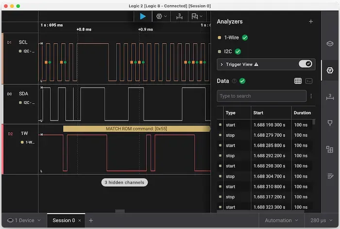
But what really makes it shine is the protocol decoder stack. The raw capture shows the actual voltage transitions, but the software can layer protocol decoders on top of that. In this case, I was able to decode the I²C side of the DS2482-100 and the 1-Wire side at the same time, which let me see both what the Raspberry Pi told the bridge to do and what the bridge actually put on the sensor bus.
Speaking Two Languages
Let’s walk through the details of how this works. Reading a DS18B20 sensor through a DS2482 is not a single “read temperature” operation. It is a conversation across two buses, with the DS2482 translating between I²C on the Raspberry Pi side and 1-Wire on the sensor side.
The Pi never talks 1-Wire directly. It sends I²C commands to the DS2482, and the DS2482 generates the reset pulses, write slots, read slots, and timing needed by the 1-Wire bus.
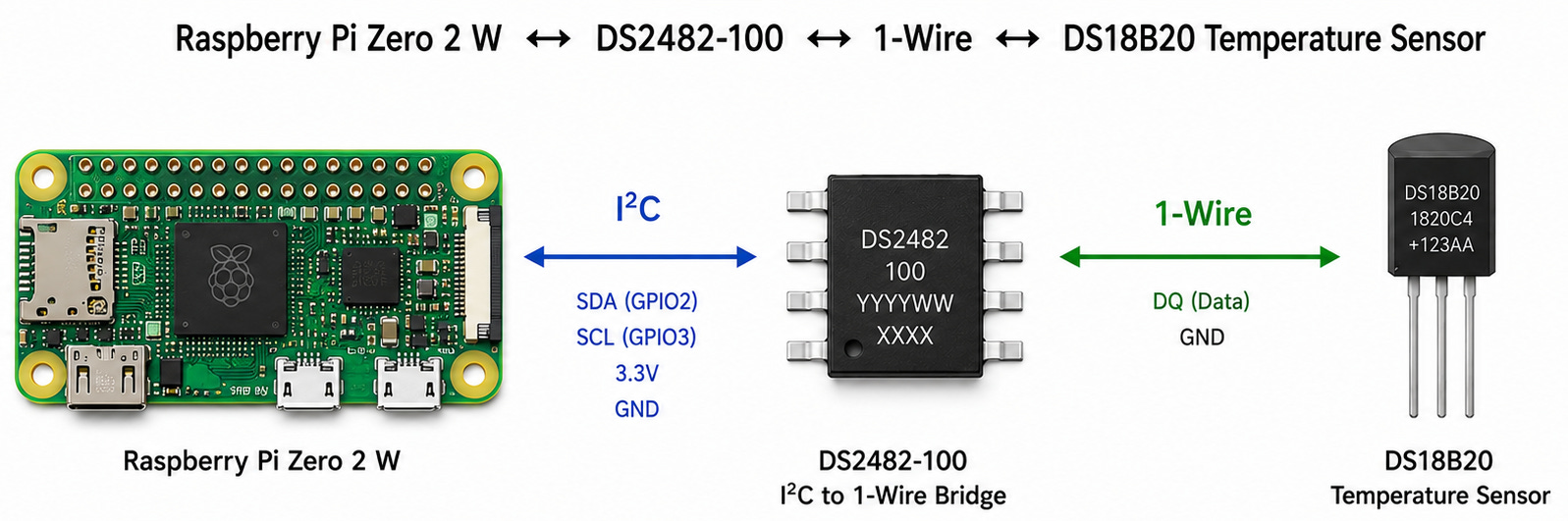
The Pi asks the DS2482 to perform a 1-Wire operation, then reads its status and data registers to find out what happened. The bridge handles the time-critical signaling, while the Pi handles the higher-level sequence: reset the bus, select a sensor, start a conversion, wait for it to finish, read the scratchpad, verify the CRC, and turn the result into a temperature.
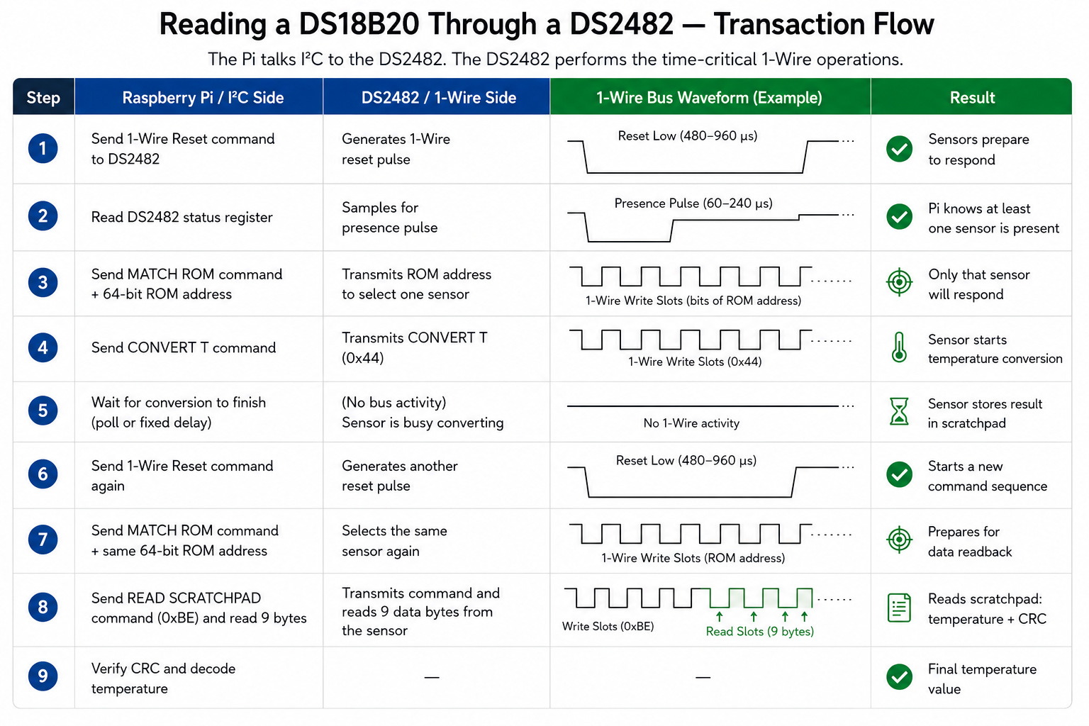
The whole exchange is easier to follow as a sequence of requests and responses as illustrated in the table below.
Following the Bytes
Now that we have glossed over the entire operation at a high level, let’s follow a temperature reading through the complete sequence using the transaction flow described in the DS18B20 datasheet.
The datasheet breaks each access into three parts: initialization, a ROM command, and a DS18B20 function command. In practice, reading a temperature requires that sequence twice—once to start the conversion and again to read the completed result from the scratchpad.
Reset and Presence Detection
Every 1-Wire command sequence begins with a bus reset. The Raspberry Pi does not generate the required timing directly. Instead, it sends a command to the DS2482, which generates the reset pulse on the 1-Wire bus.
All devices on the bus watch for this reset. If one or more devices are present, they respond with a presence pulse, briefly pulling the bus low to announce that they are alive and ready to communicate.
The DS2482 detects the presence pulse and reports the result to the Raspberry Pi through its status register. If no presence pulse is detected, there is no point continuing because no sensor is available to answer the commands that follow.
At this stage, the Pi knows only that at least one device is present on the bus. It has not yet selected a particular sensor. That comes next, using the sensor’s unique 64-bit ROM address.
Select the Sensor
Every DS18B20 contains a unique 64-bit ROM address programmed at the factory. This allows multiple sensors to share the same 1-Wire bus while still being addressed individually.
After detecting that one or more devices are present, the Raspberry Pi tells the DS2482 to send a MATCH ROM command followed by the 64-bit address of the sensor it wants to use.
Every sensor on the bus receives the command, but only the device whose ROM address matches remains selected. The other sensors ignore subsequent commands until the next bus reset.
Communication is now directed to one DS18B20, allowing the Pi to issue a command without affecting the other sensors on the bus.
The next step is to tell the selected sensor to measure its temperature.
Start the Conversion
Once the sensor has been selected, the Raspberry Pi tells the DS2482 to send the DS18B20 CONVERT T command.
The DS18B20 begins measuring the temperature and will place the result in its internal scratchpad memory when the conversion is complete. The DS2482 does not perform the measurement; it carries the command across the 1-Wire bus and handles the required bus timing.
The conversion is not instantaneous. Its duration depends on the sensor’s configured resolution, ranging from 93.75 milliseconds at 9-bit resolution to as much as 750 milliseconds at 12-bit resolution.
Wait for the Conversion
The driver must wait for the DS18B20 to finish the conversion before attempting to retrieve the new result.
It can do this either by waiting for the maximum conversion time or, when the sensor’s power arrangement permits it, by polling the bus until the sensor indicates that the conversion is complete.
Attempting to read the scratchpad too soon would not provide a reliable indication that the newly requested measurement is ready. Once the conversion finishes, the new raw temperature value is stored in the scratchpad and can be retrieved.
Reading that value begins a new 1-Wire command sequence.
Re-select the Sensor
Before reading the scratchpad, the Raspberry Pi tells the DS2482 to perform another 1-Wire bus reset and checks for another presence pulse.
The reset ends the previous command sequence, so the target sensor must be selected again. As before, the Pi tells the DS2482 to send MATCH ROM, followed by the sensor’s 64-bit ROM address.
Only the matching DS18B20 remains selected. The driver can now request the scratchpad containing the newly measured temperature.
Read the Scratchpad
With the sensor selected again, the Raspberry Pi tells the DS2482 to send the DS18B20 READ SCRATCHPAD command.
The sensor returns nine bytes: eight bytes of scratchpad data followed by a ninth byte containing the CRC. The first two data bytes contain the raw temperature value. The remaining data bytes contain alarm thresholds, configuration information, and reserved values.
The DS2482 transfers the scratchpad bytes from the 1-Wire bus to the Raspberry Pi over I²C. The Pi retrieves each byte from the DS2482 as the read progresses.
At this point, the driver has the raw sensor data, but it should not trust that data until the CRC has been checked.
Verify the CRC
The DS18B20 scratchpad contains eight bytes of data followed by a ninth byte containing an 8-bit CRC.
The driver calculates the CRC across the first eight bytes and compares its result with the CRC byte returned by the sensor. If the two values match, the scratchpad was received intact.
If they do not match, one or more bits may have been corrupted during communication, and the temperature reading is discarded rather than treated as valid.
Decode the Temperature
Once the CRC has been verified, the driver can trust the scratchpad data.
The first two bytes contain the raw temperature measurement, stored least-significant byte first as a signed 16-bit two’s-complement value. At 12-bit resolution, each count represents 1/16 °C, or 0.0625 °C.
The driver combines the two bytes, interprets the result as a signed value, and applies the appropriate scale to produce a temperature in degrees Celsius. Since this is intended for human consumption, naturally we convert it to Fahrenheit.
Enough with the Bits Already
I think that is enough geek-bit talk for one article. I will not torment you further by walking through the Saleae capture byte by byte.
Suffice it to say, the protocol decoders let me follow the entire exchange from the Raspberry Pi, through the DS2482, and out onto the 1-Wire bus. The bytes on the screen matched what the datasheet said should be happening.
Once the standalone demo was reliably talking to the DS2482, I folded that code into pIoTServer as another native driver, following the same driver framework described in Raspberry Pi Internet of Things, Part 9.
"devices": [
        {
            "address": "0x18",
            "description": "DS2482 1-Wire temperature bridge",
            "device_type": "DS2482",
            "enable": true,
            "interval": 30,
            "pins": [
                {
                    "data_type": "TEMPERATURE",
                    "description": "Plot A Soil Temperature",
                    "interval": 30,
                    "key": "PLOT1",
                    "other.props": {
                        "address": "28-9d-74-46-d4-6c-0c-4d"
                    },
                    "title": "Soil Temp Plot A",
                    "tracking": "track.range"
                }
            ],
            "title": "Soil Temperature 1-Wire Bus"
        },
  ...
]
Well, Was It Worth It?
In the end, the result was surprisingly uneventful, which is exactly what I wanted. I replaced OWFS, the FUSE mount, and the supporting daemons with a few hundred lines of code that I understood, could debug, and could maintain.
The DS18B20 sensors became just another part of the pIoTServer ecosystem, and the soil temperature values flowed through the same configuration, logging, REST API, dashboard, and automation framework as every other device in the system.
Was OWFS the cause of the strange I²C behavior I had been chasing? Methinks not. There is still the lingering odor of crappy vibe coding in the AVR firmware. But removing OWFS eliminated another moving part from the I²C bus and gave me complete visibility into what was happening from end to end.
And if nothing else, I now understand a lot more about how a DS2482 actually talks to a DS18B20. Sometimes you have to open the hood and tear out a few wires to see what is really going on underneath.
Besides, if I am going to spend two weeks debugging and cussing at code, it might as well be my code.
If you care about how things are made and enjoy ripping out the wires and cussing at them like I do, you will probably like the rest of what I write about. It is not always code. Rumor has it that sometimes I jump from baking to perfume to motorcycles without much warning.
Hitting like and sharing helps real people find the work. The algorithm can go pound sand.
Thanks Vinny for giving me a great laugh from this snippet: "...produce a temperature in degrees Celsius. Since this is intended for human consumption, naturally we convert it to Fahrenheit." I'm pretty sure most people on the planet use Celsius... are you insinuating something extraterrestrial?? 😁
I have written Dog knows how many lines of Dallas 1-Wire code, starting in 8031 assembly, then AVR assembly, and on the STM32 in C. I've bit-banged busses with 60 devices on them, then later switched to the DS2482. I've used them hard-coded in the application running on the same microcontroller, with OWFS, and as Linux devices.
I have always liked the 1-Wire bus, and it's surprisingly robust. I am, however, not that fond of using the bus to power the devices. Much better to use run a 3rd wire and supply Vcc to the devices.
Some of my favorites are the DS18B20, the iButton, the DS2401 silicon ID part (very useful before the I2C EEPROMS with a unique ID were available), and the DS2408. I spent some time also messing with the Java Ring, but it was too futzy and I couldn't think of anything to really do with it. At one time I had samples of every 1-Wire device Dallas made.
I think the first product I used a 1-Wire device on was a security key (have to go dig in the parts bin for the number), but it was a small square black rectangle that would be hung on a keyring. We had developed a voice scrambler for EF-Johnson handy talkies, and the the key was used with an 8031 based key-loader for loading the various security keys into the scrambler. We'd take about a 1 second sample of audio and divide it into 16 frames. They keys determine how the frames were re-ordered before sending, and which of the frames were frequency inverted. The decoder would receive the key at the beginning of the transmission, then reorder the frames and un-invert as necessary. It was pretty good for it's time, too. It used a Z80C15 for the processor, and had a minimum impact on the handy talkie's battery life. Good times!