
Tangled Up in Wires
How I built a RS-485 network to control my Farm Irrigation

Like most of my projects, this started as a simple problem looking for a practical solution. The farm needed a way to move the right amount of water, at the right time, to the right place, and keep doing it even when the power went out.
Easy peasy.
That was the theory, anyway. Then we became victims of our own success. The garden started growing faster than the wiring plan.
The irrigation system has gone through several stages since then, each one solving the problem directly in front of it. I wanted more than an off-the-shelf sprinkler controller.
First came the Raspberry Pi control system, which gave me flexible scheduling, local control, and environmental data collection.
Then came the first valve-control hardware: relays switching 24 VAC to ordinary sprinkler valves.
After that came the question of how to drive those same valves from battery-backed DC power. That led to the boost-and-hold experiments.
Later, I explored PWM valve control, using full power to open the valve and reduced average power to hold it open.
Each step worked. Each step also exposed the next problem.
The next problem was geography.
As the garden expanded, so did the number of zones. I could stack more PWM boards, but that only solved the controller side of the problem. Every new zone still meant more wire, possibly another trench, and another dedicated run back to the controller.

Looking at the garden from above made the problem hard to ignore. The beds were spreading out, the rows were changing, and new irrigation needs kept appearing in places that were never part of the original wiring plan. The question was no longer whether I could drive another valve. I could. The question was whether I really wanted every new valve to require another cable back to the controller.
Maybe It’s a Network?
At some point, as the valves started spreading out and the wiring kept multiplying, it became painfully obvious that this needed to be an RS-485 network. I am not sure how I missed that at the beginning of the project, but there it was.
I have spent enough time around control systems and communications links to recognize the pattern. What brought RS-485 back to mind was yet another cool project I had been working on. Once I looked back at the irrigation system, it was a natural fit.
RS-485 is an old industrial workhorse that has been around since the early 1980s. It survived because it solves a problem that never really went away: how to talk to equipment spread out over distance, in the harsh electrical environment of the real world.
A logic signal that works perfectly on a circuit board can fall apart once it has to travel down a long cable. Long cables pick up noise. Motors and relays throw garbage onto the wiring. Pumps start and stop. Ground voltage shifts from one end of the run to the other. Add conduit, wet soil, distance, and lightning weather, and suddenly a clean bench signal is not so clean anymore.
RS-485 was built for this. It sends data over a balanced pair of wires instead of relying on one fragile signal referenced to ground. The signal on one wire moves one way while the other moves the opposite way, and the receiver looks at the difference between them. Common-mode noise picked up along the cable tends to appear on both wires together. Because the receiver is looking at the difference between the two wires, it can reject much of that shared noise. That makes RS-485 much better suited for devices spread out across the farm, down long cable runs, and around pumps or other noisy equipment.

For a deeper technical overview, Texas Instruments has two useful references: RS-485 Basics and the RS-485 Design Guide. I also found the MurCal document on proper use of RS-485 Ports to be a gem.
Keep in mind that RS-485 is not a protocol. It is the wiring and signaling layer. That lets me build a simple command protocol on top of it: address a valve node, tell it what to do, and get a reply. More on that later.
Latching Solenoids
In-line automatic sprinkler valves, such as the Hunter PGV or Rain Bird CPF100, control the water used for our crop irrigation. These devices are easy to take for granted, but they are clever little pieces of engineering. I encourage you to take a few minutes and watch the video below to see how they work.
At the heart of the valve is a diaphragm and a small pilot passage controlled by a solenoid. The solenoid does not directly move all the water. It simply opens or closes a tiny control path, and the water pressure does the heavy lifting. That is the elegant part. A small electrical signal controls a much larger flow of water.
The downside is that a standard sprinkler solenoid has to stay energized the entire time the valve is open. My PWM approach makes that more efficient, but it does not change the basic problem. The controller is still feeding power to every open valve.
There is a better way: stop holding the valve open with power.
That is what latching solenoids do. They were designed for battery-powered irrigation controllers. Instead of needing continuous power, they only need a short pulse to change state. Send current one direction and the valve opens. Send it the opposite direction and the valve closes. After that, the driver turns off and the valve stays where it was.
What put me off at first was my assumption that latching solenoids would be expensive, obscure, or hard to source. I thought this was some esoteric European thing.
As Ron White would say, “I was wrong.”
The Hunter 458200 DC latching solenoid was only a few dollars more than a standard replacement solenoid. Rain Bird offers a similar latching solenoid, the K80920, though it costs a bit more.
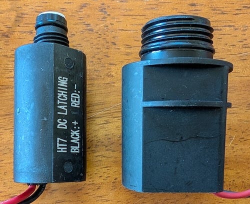
As you can see in the photo, Hunter and Rain Bird solenoids use different thread designs, so they are not mechanically interchangeable. Electrically, however, they work the same basic way. They still use two wires and are controlled by the direction of current flow.
The good news is that within a given brand, standard and latching solenoids are generally interchangeable on compatible valve bodies. That meant I did not have to abandon ordinary irrigation valves. I could keep the same basic valve bodies and simply change the solenoid.
Even though the latching solenoids are technically not motors, but the control problem is similar to the lock actuator I used in the chicken coop project. Current one way moves the plunger one direction. Current the other way moves it back.
And it turns out that the VNH7100BAS H-bridge, like the one I used in my Humble Actuator project, is a natural fit for controlling the polarity. It might even be a bit of overkill, but when these valves get wet, dirty, old, or sticky they are a bargain at around $2.50 a piece.
The 30,000-Foot View
The architecture is simple: one master, many valve nodes.
I designed two boards for this system: a master board and a valve node board. The master sits near the Raspberry Pi and manages the RS-485 field bus. The valve nodes live out closer to the valves and drive the latching solenoids.
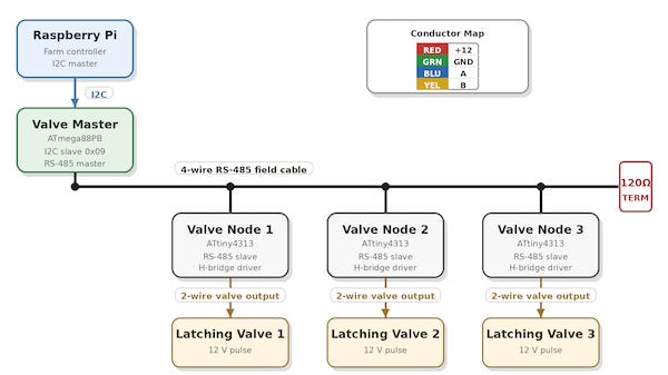
The Raspberry Pi still runs the irrigation logic. It decides what should happen and when. The master board translates those decisions into RS-485 commands. Each valve node listens for commands addressed to it, pulses the right solenoid in the right direction, and reports back.
Instead of running every valve back to the controller, I can run a shared four-wire cable through the field and hang valve nodes off that cable. Two wires carry 12 VDC power. The other two carry the RS-485 data pair.
The protocol is intentionally simple. At the electrical level, it is a 9600 baud serial line running over RS-485. The master sends a command to a specific valve node, and the node either acts on it or reports back: open a valve, close a valve, identify yourself, or report how many valves it can control.
If you want the deep details, I have made the schematics, board layouts, KiCad files, firmware, protocol notes, and test tools available in the ValveNode GitHub repository.
Valve Master Board
The first board is the Valve Master. This board stays near the Raspberry Pi and acts as the bridge between the main farm-control software and the irrigation field bus.
On one side, it talks to the Raspberry Pi over I2C. On the other side, it controls the RS-485 cable that runs out into the field. It also switches the 12 V field power, so the valve-node network does not have to sit powered all the time.
The master board does not directly open and close every valve. That is the point. Its job is to manage the bus, send commands to the valve nodes, receive replies, keep track of which nodes are out there, and report results back to the host.
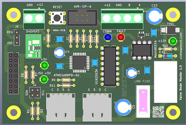
I designed the I2C side so the board can be built two ways: as a NodeLync-compatible device hanging off the shared I2C bus, or as a daughter card that plugs directly into my Raspberry Pi irrigation controller. The hardware is built around an ATmega88PB-AU microcontroller, a MAX485-style RS-485 transceiver, a relay-switched 12 V field output, status indicators, and an AVR programming header.
Nothing exotic. Just the pieces needed to turn a Raspberry Pi command into a field-bus command that can survive outside the controller box.
The Raspberry Pi decides what should happen, sends the command over I2C to the Valve Master, and the Valve Master handles communication with the nodes in the field.
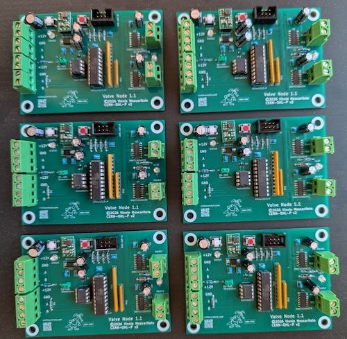
Valve Node Board
The valve node board lives out near the valves. It has the RS-485 interface, a small microcontroller, input protection and power conditioning for the incoming 12 V field supply, and the H-bridge drivers needed to pulse the local latching solenoids. Each node has an address, so the master can tell one specific board to open or close one specific valve.
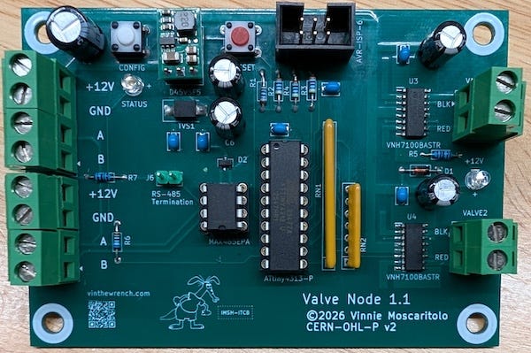
Since this board literally lives out in the field, I designed it to fit comfortably inside a common 2FSE FS outdoor electrical box, protecting the electronics from the usual outdoor abuse while leaving enough room for wiring, strain relief, and service access.
Even with the microcontroller, RS-485 transceiver, H-bridge drivers, input protection, voltage regulation, terminal blocks, and the PCB itself, this is still a modest-cost board. In small quantities, I am roughly in the $30 to $45 range per valve node, not counting assembly, shipping, or tariffs.
You do not have to use the Valve Master board to use the valve nodes. The nodes speak ordinary 9600 baud serial over RS-485, so any controller that can send the right frames over an RS-485 interface can talk to them. A USB-to-RS-485 adapter, such as the Waveshare USB to RS232/485 Serial Converter, is enough for direct testing. In fact, that is how I did my initial debugging.
The ValveNode Protocol
This project does not need a complicated protocol. It only needs enough structure for the master to send a command over a 9600 baud RS-485 serial line to a valve node, get an acknowledgment back, and handle a small set of operations: open a valve, close a valve, report status, identify itself, or report how many valves it can control.
I implemented the protocol as a simple ASCII frame format. It is easy to type, easy to log, and easy to debug from a terminal. That way I could connect a USB-to-RS-485 adapter, type commands by hand, and see exactly what came back.
The bus is master-controlled. Nodes do not chatter whenever they feel like it. The master sends a request, and only the addressed node replies.
The frames are short ASCII messages. Each command starts with a marker, includes the target node address, a command code, any needed argument, and ends with a carriage return. Replies use the same basic idea, with an acknowledgment, status, or error result coming back from the addressed node.
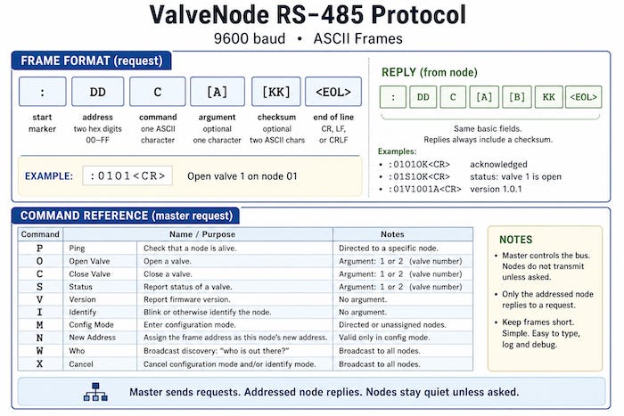
For example, to tell node 5 to open valve 1, the master sends:
:05O1<CR>
That means: address node 05, send the open command, and pass valve 1 as the argument. If the node accepts the command, it replies with `A` for acknowledged:
:05A<CR>
A slightly more complicated example is the WHO command, which asks the bus which nodes are connected. The master broadcasts a W command to all nodes by sending it to the FF address:
:FFW<CR>
The tricky part is the reply. If every node answered at the same time, they would talk over each other and the bus would turn into garbage. To avoid that, each node waits for a short delay based on its address before replying.
For example, if nodes 1, 4, and 18 are on the bus, the master might see replies like this:
:01W<CR>
:04W<CR>
:12W<CR>
Each node waits in a 20 ms slot based on its address before replying. Node 1 waits about 20 ms, node 4 waits about 80 ms, and node 18 waits about 360 ms.
The master just has to keep listening long enough for the highest expected node address to answer. For example, if I allow up to 32 nodes, the discovery window needs to be a little over 640 ms, plus some margin.
Note: Addresses are written as two-digit hex values, so node 18 shows up as
12in the reply.
The messages include a checksum so the devices can detect corrupted messages. The checksum is simple: add up the bytes in the message payload, keep the low 8 bits, and send that value as two hex digits at the end of the frame.
I left the checksum out of the examples above to keep them readable. The valve node firmware will also accept simple commands without one, which makes hand testing from a terminal much easier.
It is not cryptography, just a quick sanity check to keep noise on the line from causing havoc.
Building and Programming the Boards
Once the boards are assembled, they still need to be programmed. Both the master and node boards use AVR microcontrollers, and each board runs its own firmware. The code that runs on the boards is written in C and built with the AVR toolchain, and loaded using avrdude.
Both boards include provisions for a 6-pin AVR ISP connector that mates with an Atmel-ICE programmer.
In previous articles, I wrote in more detail about building AVR code and downloading it to the chip, including “avrdude: The Debugging Tool You Didn’t Know You Had” and “How Did You Make That.”
A newly programmed valve node starts out unconfigured. Before it can join the RS-485 bus, it needs a unique address.
After flashing the firmware, I connect each new node to the RS-485 bus by itself, put it into configuration mode, and assign it an address.
For example, to configure a fresh node as node 7, I send:
:07N<CR>
That tells the unconfigured node to store address 07 in EEPROM. After that, it responds as node 7 on the bus.
Then I can test it with a ping:
:07P<CR>
If everything worked, the node replies:
:07A<CR>
The address can also be changed later by putting that node back into configuration mode and sending it a new address command.
Test Tools and Diagnostics
Before these boards go into outdoor boxes, it is useful to have good ways to test and diagnose them on the bench. I can manually send commands through a terminal emulator over a USB-to-RS-485 adapter, but I wanted something a bit more intuitive to use. So, like any good programmer, I wrote some test utilities.
The first one is vnode, a command-line tool for talking directly to valve nodes over a serial port. It assumes a USB-to-RS-485 adapter is connected to the bus. From there, vnode can ping a node, open or close a valve, check status, ask for the firmware version, identify a node, run discovery, assign addresses, move a node to a new address, cancel configuration mode, or send a raw frame by hand.
For example:
$ ./vnode -d /dev/ttyUSB0 who
device: /dev/ttyUSB0
baud:   9600
tx: :FFW\r
rx: :01WB8  [checksum ok] node=1 WHO
rx: :02WB9  [checksum ok] node=2 WHO

$ ./vnode -d /dev/ttyUSB0 ping 1
device: /dev/ttyUSB0
baud:   9600
tx: :01P\r
rx: :01AA2  [checksum ok] node=1 ACK

$ ./vnode -d /dev/ttyUSB0 open 1 1
device: /dev/ttyUSB0
baud:   9600
tx: :01O1\r
rx: :01AA2  [checksum ok] node=1 ACK
That gives me a quick way to discover nodes, verify that a node is answering, and command a valve output without involving the Valve Master or the Raspberry Pi irrigation software. It can also be used to configure a fresh node, assign its address, and verify that it answers before it goes into the field.
The other utility is valve, which talks to the Valve Master over I2C, the same way the Raspberry Pi irrigation software would. That lets me test the full chain: Raspberry Pi side, I2C, Valve Master, RS-485, valve node, and finally the latching solenoid output.
The valve tool can:
Check master status
Switch field power on or off
Discover nodes
Ping a node
Open or close a channel
Check channel status
Read master or node firmware versions
Identify a node
Handle address provisioning
The GitHub repository also includes test scripts, including hammer.sh, which repeatedly exercises the full Valve Master path. In bench testing, it completed 500 loops across five nodes, 10,016 commands total, with zero first-try failures.
About Those Tangled Wires
There is nothing wrong with reusing the 18 AWG sprinkler wire I already had in place. It was already buried, already routed to the right places, and for short runs it was perfectly serviceable.
But anywhere I was pulling new cable, I wanted something better suited to this design. The RS-485 data side is not the hard part at 9600 baud. The real issue is getting enough 12 V power out to the valve nodes over a few hundred feet of wire.
For new runs, I settled on 16 AWG, 4-conductor, stranded copper, direct-burial cable I came across online.
Two conductors carry +12 V and ground, and the other two carry the RS-485 A/B pair. Twisted pair would be nice, but copper, gauge, and burial rating matter more here than perfect data-cable theology.
Good Systems Evolve
This is not a completely different irrigation system. It is the next step in the same one.
The project started with a simple question: how do I drive ordinary sprinkler valves from a Raspberry Pi and keep them working when the power goes out? The answer kept evolving as the garden grew: relays, DC boost-and-hold, PWM, and now latching solenoids on an RS-485 field bus.
That reminded me of Donald Knuth’s old warning that “premature optimization is the root of all evil.” I had spent a lot of effort making ordinary sprinkler solenoids more efficient. The better move was to stop holding the valve open with power in the first place.
That is how good systems evolve. You solve the problem in front of you. If the system is useful, it grows. If it grows, it eventually shows you where the old design runs out of room.
Post Scriptum
After letting the invisible magic smoke out of two Rain Bird latching solenoids, I started wondering whether I had configured the valve node drivers wrong.
Rain Bird does not exactly give you engineering data for these parts, but I had seen them described as 9 V latching solenoids. Why should they, you should be using it with their hardware.
My first reaction was, “yeah, yeah, so what?” I was only hitting them with short pulses.
Then two of them stopped closing reliably after a day of cycling.
OK. Time for engineering.
The field bus is 12 V, but that does not mean the solenoid needs to eat the full 12 V pulse. The Rain Bird solenoid I measured was about 7.2 ohms. I added a 2.2 ohm resistor in series with the solenoid drive path, giving a total resistance of about 9.4 ohms.
Using Ohm’s law:
I = V / R
I = 12 V / 9.4 ohms
I ≈ 1.28 A
The solenoid itself then sees roughly:
V = I × R
V = 1.28 A × 7.2 ohms
V ≈ 9.2 V
That lets the field bus stay at 12 V while bringing the solenoid pulse down into the neighborhood of a 9 V latching-solenoid pulse. I also shortened the firmware pulse to 20 ms. The resistor is not being used as a continuous power device. It is only there to take the edge off a short actuation pulse. So far, 2.2 ohms 1 Watt resistor in series with the solenoid works fine.
If you care about how things are made and why they’re built the way they are, you’ll probably like the rest of what I write about. It is not always electronics. Believe it or not, I have been known to jump from baking to perfume to motorcycles without much warning.
Hitting like and sharing helps real people find the work. The algorithm can go pound sand.
Yes, thank you. I appreciate your feedback. What you see here is the tip of the iceberg. Reading back to my original article. This is all hooked up to a Raspberry pi/ Linux box that is running some intelligence. We've been tracking our soil temperature rainfall air temperature for quite a while now. There's another reason I've designed it this way and the most likely the most important.. when you buy into the hunter/ rain bird ecosystem you are stuck with them. And you are stuck with what they decide the software should look like. And if they are cloud managed, you are stuck with cloud management systems. If there's a denial of service attack on their cloud, you're out of luck. You out of luck. I've seen the exact same thing happen with dab pumps. I love their hardware about whoever wrote their software. Did it prevent you from stepping out of their ecosystem?.. so yeah I appreciate what you're telling me. It's just part of a bigger picture that's all
Hey Vinnie…You're my kind of guy!
Sounds like a fun, geeky project!
May I only add this: I'm a professional Landscape Architect; it's my business to design and specify complex irrigation systems. There are many features nowadays on clocks, valves and other appurtenances like custom-regulation when there's been rainfall on controllers offered by Hunter, RainBird, Toro, et.al., that provide much more functionality as well as use of a single wire system (this one is huge). They are a breeze! And, I imagine, much less expensive.
OTOH, not nearly as much fun as this project…lol.
ps: There's also lots of design help/advice t your local irrigation distributor.